
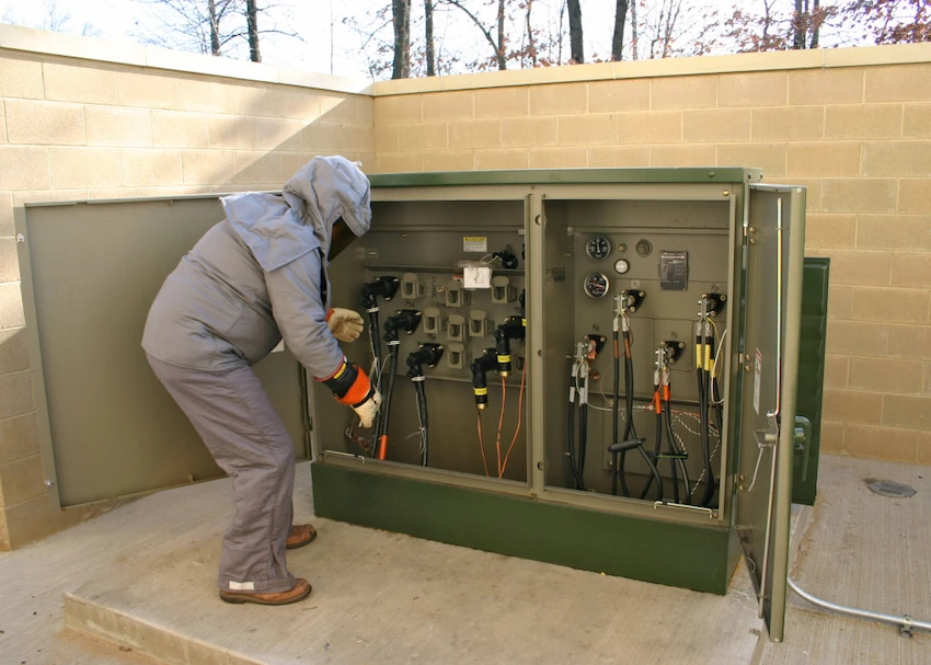
How to Choose Pad Mounted Transformer?
Table of Contents Selecting the right pad-mounted transformer requires careful consideration of several critical
ELECTRIC, WITH AN EDGE
Distribution transformer losses account for 40-45% of the total losses of all transformers in the power system.
In the comprehensive calculation of power system economics, many power companies are trying to evaluate the performance of transformers from the aspects of power system investment, loss, reliability and sensitivity.
In recent years, the energy crisis has drawn people’s attention to the energy consumed in the process of energy production and use.
For power systems, it also focuses on reducing losses on transmission lines and their equipment.
The peak losses and annual average losses of various types of transformers on a representative 5000 MW transmission line are shown in Table 1.
It can be seen from Table 1 that although these losses only account for 20-25% of the total losses in the power system, they are still considerable and must be considered in the design of power systems and transformers.
In particular, the loss of distribution transformer accounts for 40-45% of the total loss of all transformers in the system, which attracts people’s attention.
Due to the escalating energy costs, many power companies try to evaluate transformer performance.
They try to examine all the data as objectively as possible so that they can pay for the transformer’s energy losses and its price, as well as reliability, availability and sensitivity characteristics.
The power companies are very concerned about the overall economics of the power system.
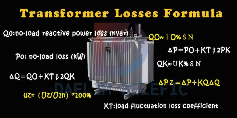
The total losses of distribution transformers include active losses (no-load and load), reactive power losses (no-load and load), and voltage regulation losses.
Because each type of loss affects the additional energy and general energy of the power system, there are additional energy and general energy cost components in each loss, which will be described later in this paper.
In order to calculate the loss cost correctly, additional energy and general energy cost need to be discussed separately.
The equation for the average annual total cost of a distribution transformer is listed in simplified form as follows:
Average annual total cost = (power company distribution transformer cost x average annual fixed cost rate) + annual additional energy cost for no-load and load losses + annual general energy cost for no-load, load and regulation losses + no-load and load losses The annual reactive energy cost is the annual pressure loss cost of additional energy.
The active loss of a distribution transformer can be divided into two components: no-load loss and load loss.
No-load losses include eddy current losses, hysteresis losses, I2R losses and dielectric losses caused by excitation current.
Because most of these losses are due to the loss of the transformer core silicon steel sheet, the no-load loss is usually referred to as the iron loss of the distribution transformer.
Load losses are I2R losses in distribution transformer coils, eddy current losses induced by stray magnetic flux in distribution transformer structures, and similar losses that vary with load current.
Over the years, however, the terms “load loss” and “copper loss” have been used interchangeably and have been generally accepted in practice.
Many distribution transformers in manufacturers today are designed with aluminum coils, and the term “copper loss” is no longer appropriate.
Distribution transformer losses affect utility companies in two ways.
First, the kilowatt-hours spent in losses must be supplied by the power plant, and the fuel cost and other production costs to generate these dry watt-hours must vary with the transformer used. This component is often referred to as the general energy cost or production cost component.
The second component is often referred to as the additional energy cost.
It is variable and represents the additional lost kilowatt-hours that additional equipment needs to provide, usually referring to peak losses.
Although no-load losses are essentially constant during operation, there are periodic peak loads on distribution transformers, so the power system must have additional equipment to supply additional kilowatt-hours.
The additional annual energy cost for no-load losses is:
Additional energy cost (when no load) = iron loss x investment cost of power system x average annual fixed cost rate.
The general energy cost depends on the average incremental cost of power supplied by a generator with sufficient load capacity.
Since iron losses are essentially constant during operation and energy is typically supplied by the more efficient main generator most of the time, the typical annual energy cost for no-load losses is:
General energy cost (no load) = iron loss * 8760 * cost of energy production increasing year by year.
In distribution transformers, the loss due to peak load may occur at the same time when the peak load is the maximum value of the system load, or it may not, but the generator still has to bear the maximum load value.
This leads to the introduction of a new term for calculating peak load losses.
The peak load factor = the load of the distribution transformer at the peak of the system + the peak load of the distribution transformer.
The peak load factor of each power company is different, and the peak load factor values of various types of distribution transformers are generally shown in Table 2.
The additional annual energy cost for load loss is:
Additional energy cost (when loaded) two load loss * (transformer annual peak load x peak load factor) 2 * system investment cost * average annual fixed cost rate.
It must be noted that the additional component energy of load loss includes the influencing factors of various aspects of load loss.
At this time, it is mainly necessary to consider the loss of the distribution transformer at the peak of the system, rather than the loss of the distribution transformer at the peak, because the peak load factor is multiplied by the peak load of the distribution transformer and then squared.
Use the load-time curve to determine a term known as the “load factor,” which is defined as:
Load factor = kilowatt-hours loaded during the specified time period + (hours in the period x peak load).
Average load is expressed as a percentage of peak load.
Because one is interested in the number of kilowatt-hours lost in a year, one must study the loss-time curve, which is obtained by squaring the load-time curve, and then averaging the area enclosed by the curve.
This leads to another term – loss factor.
It is defined as:
Loss factor = kilowatt-hours lost in a specified time period + (hours for that period * peak loss).
To correctly describe the derivation of loss coefficients, a large amount of data is required.
Thanks to the actual load-time curves measured on various types of transformers, a lot of research work has been done.
A general formula for the relationship between the loss factor and the load factor, which is easier to determine, has been derived.
The formula in the application is as follows:
Loss factor=C*(load factor)+(1-C)*load factor)2.
where C is a constant, usually C=0.15~0.30.
The typical annual energy cost for load loss is:
General energy cost (when loaded) = load loss * (transformer peak load per year) 2 * 8760 * annual loss factor of distribution transformer x incremental cost of energy production.
Also, since it is better to use the actual loss factor serving a large number of users, rather than just the loss factor of the power system or distribution system.
Therefore, the general energy component also includes the effect of load loss changes.
This loss factor is applied to the peak losses at the peak of the transformer.
The reactive power loss of the distribution transformer is divided into two parts, namely the no-load reactive power loss (or the reactive power component KVA of the excitation power) and the load reactive power loss l (I2* loss).
The no-load and load reactive power losses of distribution transformers are usually supplied by variable and fixed capacitors respectively connected to the primary side of the distribution transformer.
The annual cost of no-load reactive power loss is:
No-load loss cost (reactive power) = [(transformer rated voltage) 2 * (transformer magnetizing current) 2 – (iron loss) 2] 1/2 * cost of installing fixed capacitors * average annual fixed rate.
When the system has a peak load, if the cost of load reactive power loss is determined, the corresponding relationship between the transformer load and its peak load must be considered.
For reactive power losses, a similar term, peak load factor, will also be used to establish the relationship between the distribution transformer peak load and the distribution transformer load at system peaks.
That is, the load factor of the primary line at the peak value = the transformer load at the peak value of the primary line + the peak load of the transformer.
The annual cost of load reactive power loss at peak load on the primary line is:
Load loss cost (reactive power) = [(transformer rated voltage) 2 * (transformer impedance) 2 – (load loss) 2] 1/2 * (transformer peak load per year * primary line load factor at peak) 2 * installation is possible Variable Capacitor Fee* Average annual fixed cost rate.
The voltage regulation or voltage drop of the distribution transformer affects the additional energy and general energy of the system, and it also affects the equipment required by the system and the net profit obtained from the sensitive voltage regulation and the voltage regulation characteristics that satisfy the user.
One way to calculate the pressure regulation loss is to calculate the pressure regulation cost (saving value) of the transformation when additional energy is added each year as:
Annual additional energy cost (voltage regulation) = (transformer rated voltage x annual peak load of transformer * peak load factor * load power factor) * (transformer voltage regulation value at rated load * annual peak load of transformer * peak load factor * voltage change 1% kWh per load change) * system investment fee x average annual fixed cost rate.
The term in the first parenthesis in the formula represents the load at the peak of the system, calculated in kilowatts.
The second parenthetical term represents the transformed energy or added regulator equipment at the peak of the system.
The annual cost of voltage regulation for general energy, or the profit lost due to voltage regulation conversion in general energy, minus the cost of energy consumed by the power company itself is:
General energy cost (voltage regulation) = (transformer rated voltage * transformer peak load per year * load power factor * 8760 ) * (transformer voltage regulation value at rated load * transformer peak load per year) \ (kW of load change when voltage changes 1% number * annual loss factor of transformer) * (average selling price of energy required by users – average annual fixed cost rate).
The first bracket indicates the general energy sold per year.
Calculated in kilowatt hours. The second bracket indicates the regulating value or regulating device.
Transformers are static electrical equipment, so there is no mechanical loss in the energy transfer process, so their efficiency is higher than that of rotating electrical machines.
Generally, the efficiency of small and medium-sized power transformers is above 95%, and the efficiency of large-scale power transformers can reach more than 99%.
The losses generated by the transformer mainly include iron losses and copper losses in the primary and secondary windings.
The iron loss of the transformer is the hysteresis and eddy current loss in the iron core, which is determined by the magnetic flux density in the iron core, the frequency of magnetic flux alternating and the quality of the silicon steel sheet.
The iron loss of the transformer is approximately proportional to the power supply voltage U21 applied to the primary winding, and has nothing to do with the size of the load.
When the power supply voltage is constant, the iron loss of the transformer is basically unchanged, so the iron loss is also called “constant loss”.
The basic copper loss in the copper loss of the transformer is the loss I21Rk of the current on the DC resistance of the primary and secondary windings.
The magnitude of the transformer copper loss is proportional to the square of the load current, so it is called “variable loss”.
The approximate loss per hour is about 135KW. At no load, it consumes about 1.15*24*30=828kw per month; at full load, it consumes about 10.3*24*30=7416 kWh.
Transformer losses are divided into two parts:
1. No-load loss, mainly iron loss, consists of hysteresis loss and eddy current loss.
2. The load loss, mainly copper loss, is proportional to the square of the load current. Therefore, the greater the load, the greater the loss.
It can be seen that no matter how much electricity is used, its own loss cannot be 0.
The difference between the electricity measured by the power supply company and the electricity of each sub-meter of your company (the loss you mentioned) mainly exists as follows:
1. Transformer loss: no-load loss (iron loss), which is fixed and can be checked for information; load loss (copper loss), which is related to the load and increases in geometric proportion with the load. Similarly, the full-load copper loss is also It can be obtained from the information, and the specific copper loss should be calculated by applying the formula according to the load rate.
2. Electric energy metering device error: There are positive and negative errors in the electric energy metering device (electric energy meter, current transformer, voltage transformer) of the power supply company. Similarly, the electric energy metering device of your company (electric energy meter, current transformer, voltage transformer) also has Positive and negative errors.
3. Part of the loss will be generated in electrical equipment such as busbar, circuit breaker, isolating switch, etc., but it is very small and basically ignored.
The loss rate of distribution transformers depends on the amount of electricity used.
The on-load loss of the distribution transformer should be a little more than 1%, and the no-load loss is less than 1%.
However, it is necessary to consider whether it is an energy-saving type. Some old-fashioned distribution transformers have higher losses and even reach 3%.
Generally, S9 distribution transformers can be used later. The monthly loss of a 200kw transformer should be around 800-1500 kWh, depending on the utilization rate of your load.
The parameters used in the loss calculation formula have obvious influence on the result of calculating the loss cost of distribution transformer.
The parameters selected by different power companies to realize these calculations are not the same.
Some considerations for the selection of these parameters are discussed below:
When considering the interrelationship between the size of a distribution transformer and its no-load and load-loss costs, it is found that for the no-load and load-loss values of each product, there is an average annual minimum total when designing the transformer. question of cost.
Due to the large variation range of the parameter loss, the design of one transformer may be beneficial to the calculation of one power company, but it may be unfavorable to the calculation of another power company.
For distribution transformers of the same design, the economics are related to mass production, which means that it is not economical for each power company to produce the truly optimal distribution transformer.
All major distribution transformer manufacturers in China use a wound core as the basis for their design, which makes the distribution transformer in the United States
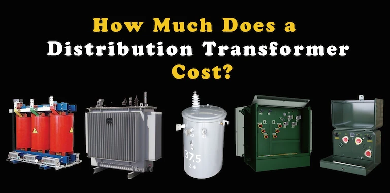
This explains why the cost of distribution transformers and power transformers is very different.
Still, the most expensive ingredient is usually in the distribution transformer.
The computer can not use the parameters in the formula to design the transformer, but the manufacturer can do the following considerations: If the use requires short-circuit strength, it means that the impedance needs to be higher;
If the load capacity is required, in order to ensure this requirement, the lower loss rate of the distribution transformer cannot be guaranteed; if the use requires overvoltage operation, it means that the excitation current is lower at the rated voltage.
Although the designers are limited to use the wound iron core, there is still a problem of application selection in the design.
As system investment and energy costs continue to increase, it would be beneficial for many utilities to attempt to evaluate distribution transformer performance, and they strive to derive consistent methods for distribution transformer loss calculations.
To ensure an optimally designed transformer consistent with actual use, the system and cost parameters should be carefully selected when applying the calculation formula.
Download Resource
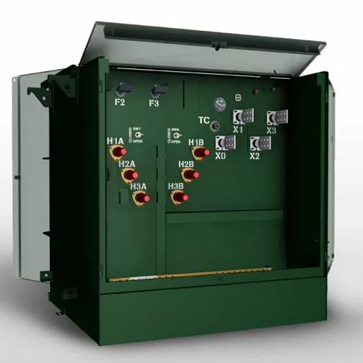
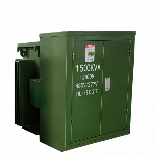
Table of Contents Selecting the right pad-mounted transformer requires careful consideration of several critical

The primary function of the pad mounted transformer is to serve as a critical distribution

A pad mounted transformer operates through electromagnetic induction, serving as a crucial distribution component that
After filling in the contact information, you can download the PDF.