
How to Choose Pad Mounted Transformer?
Table of Contents Selecting the right pad-mounted transformer requires careful consideration of several critical
ELECTRIC, WITH AN EDGE
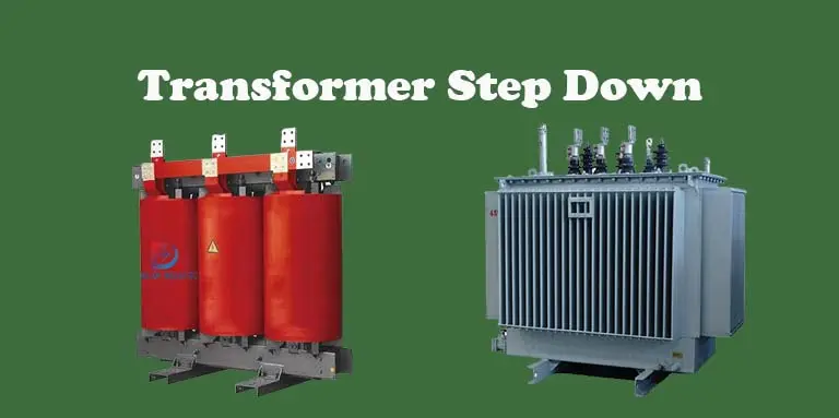
A transformer Step Down converts the input high voltage and outputs it to a low voltage.
The step-down transformer principle is to use electromagnetic principles to convert.
But there are many kinds of step-down transformers on the market, so which transformers can step down?
This article will tell you in detail.
If you need to purchase a step-down transformer, daelim can undoubtedly be your first choice.
Daelim has obtained multiple standards, such as CSA, IEEE, SGS, CNAS, CESI, etc.
This means that Daelim provides you with high quality and reliable step-down transformers.
If you have special needs, please inform daelim, Daelim even has a professional on-site installation team in North America, which can allow you to complete the whole process monitoring of step-down transformers from purchase to installation in the office.
If you want to lower the voltage (HV) and current (LV) from the primary to the secondary side of the transformer, you will need a transformer step down, which is a transformer that does it and is being promoted by Daelim.
In context, it transforms electrical energy into magnetic energy, then back to electrical energy.
Electrical systems and transmission lines benefit from the use of transformer step down .
Because the secondary winding has fewer turns than the primary winding, the secondary voltage is lower than the primary voltage.
Consequently, a Step Down Transformer transformer of this sort is employed to lower the voltage to the desired values for the circuit.
Power sources with transformer steps are almost universally available. Electronic Step Down Transformers and distribution systems commonly utilize these transformers.
On the other hand, reversible machines, like transformers, can be used to step up or step down the voltage applied to them.
The HV terminals would be connected to the system in the case of a high-voltage circuit, whilst the LV terminals would be used in the case of low-voltage circuits and loads.
Then, the transformer’s voltage is proportional to its turn ratio.
We can increase the voltage by increasing the number of turns in the winding.
Low voltage is achieved by reducing the number of turns on the secondary winding, while the primary winding is larger so that it can withstand higher voltages.
To power low voltage AC equipment, the Step-Down Transformer converts high voltage (208 or 200 VAC) output into low voltage (120 or 100 VAC).
There are a variety of rack-based designs available in this family of items available at Daelim.
As with previous APC products, you can expect a similar look and feel from this one. Despite their small size, they can provide up to 4.5kW of power to your load.
The unit of measurement is the metric equivalent to 1.75 U. 208 volts is stepped down to 120 volts before being distributed to the loads. 208V APC Symmetra and Smart-UPS 208V devices are compatible with them.
In a power system, transformers step-down play a critical role.
In order to better serve the needs of consumers, they lower the voltage.
As a reminder, the voltage should be as high as possible for long distance energy transfer.
Transmission losses will be greatly reduced if the voltage and current are high.
In order to link to the transmission system, a power grid with various voltage levels must be developed.
In addition, it is common practice to employ step-down transformers to connect transmission networks of differing voltage levels together.
For example, 765/220 kV, or 410/220-kV, or 110/110 kV, are examples of voltage levels that are reduced from high to low.
These step-down transformers are massive and have a lot of rated power (even 1000 MVA).
Auto transformers are commonly used in this situation because the transformer turns ratio isn’t very high.
Therefore, transmission voltage is then adjusted to the distribution level, which is followed by a transformation of the voltage levels.
In this instance, the voltage ratios are 220/20 kV and 110/20 kV.
These transformers have a nominal output of up to 60 MVA. These transformers are usually always equipped with an on-load tap changer.
The tap changer’s primary function is to regulate voltage.
LV tap changers are more common in the United States, while HV tap changers are more common elsewhere.
In the final step of voltage transformation, the voltage is adapted to match the voltage level in the residence.
Further, small distribution transformers have a nominal power of up to 5 MVA (usually below 1 MVA) and a nominal voltage of 35, 20, or 10 kV on the HV side and 400/200 V on the LV side, making them suitable for a wide range of applications.
The high turns ratio of these transformers step-down may be seen.
They typically have a de-energized tap changer with five tap positions (plus or minus two tap positions) and no on-load tap changer.
440 volts is the peak voltage at which AC electricity is generated in power plants.
The most common voltage for households and businesses is between 220V and 240V.
Using a step-up transformer, the power station’s generated voltage is raised to several kilovolts at its highest point.
A high-tension transmission line carries the power/electricity over long distances using the step-up transformer’s output.
Reduced voltage drop is the goal here.
To achieve 220V-240V, the power must first be stepped down using a transformer step-down before it can be used at the final consumption point/end substation.
Wires known as coils wind the voltage step-down transformer.
Wires with low resistance and good conductivity are used here since they are essential to maximizing the transformer’s efficiency.
A common choice for transformer windings is copper because of its high electrical conductivity and low resistance.
Furthermore, it isn’t prohibitively expensive in comparison to precious metals like gold, silver, and platinum.
In relation, the “Faraday law of electromagnetic induction” governs transformer operation.
Mutual induction between windings in a transformer is the driving force behind its operation.
A change in the magnetic flux linking a circuit induces an electric charge proportional to the flux linkage’s rate of change, according to Faraday’s law.
The number of turns in the primary and secondary windings influence the emf (ElectroMotive Force) generated between them.
As a result of this ratio, the Turns Ratio is named.
Consequently, the step-down transformer’s ability to reduce voltage is dependent on the primary and secondary coils’ turn ratios.
The quantity of flux linkage to the secondary coil of the transformer will be less than the primary coil because of the lower number of windings in the secondary coil.
As a result, the secondary coil will experience less induced emf.
Because of this, the secondary winding voltage is lower than the primary winding.
Mutual induction is the basis of a transformer’s operation.
If the current in one coil fluctuates, the other coils nearby will also experience an electric current.
The primary and secondary windings of a transformer step-down are made up of two coils. It is connected to the AC power source by the primary winding, and to the load via the secondary.
A magnetic flux is formed when AC current is applied to the primary winding of the coil.
The magnetic field completes its journey through the transformer core.
An EMF is generated on the secondary winding when it comes into touch with this magnetic flux.
The number of turns in the secondary coil winding affects the strength of the generated EMF.
Each bundle of copper coils within a transformer winding is linked together to form a winding.
The input-output supply and, to a lesser extent, the voltage range, determine the performance of windings.
Primary winding and secondary winding are two forms of step-down transformer winding.
Basically, the primary winding receives electricity from the source, while the secondary winding distributes it to customers.
Therefore, aluminum and copper are the most commonly utilized conductors in transformer windings, respectively.
Copper has excellent mechanical strength and conductivity, however aluminum is less expensive and lighter than copper.
Large transformers typically employ copper windings, whereas smaller transformers step-down use aluminum conductors.
Keeping the initial cost of the transformer winding to a minimum is critical to success.
In addition, windings have lower operating and maintenance costs.
For the heating condition to meet the criteria, it must do so.
The transformer’s lifespan is severely shortened if its windings aren’t able to handle the increased temperature.
Additionally, it is imperative that the winding remain stable in the event of an unexpected short circuit in the transformer step down.
The winding must be able to withstand an overvoltage.
From the perspective of insulation, the location of the HV and LV windings is critical.
Two layers of insulation are required if the HV winding is located close to the transformer core; the core and the LV winding.
Only one layer of HV insulation is needed if HV winding is put on the outer side and LV winding is placed close to the core.
This layer of insulation is sandwiched between the high-voltage and low-voltage windings. Insulating varnish is put into the core before the coils are joined with the core.
The rectangular cross-legs section’s make it the simplest to construct the core.
As a result, a rectangular-coil transformer is the most cost-effective option.
In connection, rectangular concentric coils are employed in the construction of compact transformers step down because of their portability.
The high repulsion forces generated between the primary and secondary coils in the case of the big unit under short circuit conditions.
The outer coil’s flat sides are “rounded out” as a result of this process.
In the event that this occurs, the insulation of the coils is damaged.
In the worst-case scenario, the transformer is rendered unusable by the damage.
Cylindrical concentric coils are utilized to avoid this problem in transformers with big units.
It can be either concentric or sandwich depending on how the HV and LV windings are arranged.
Core transformers use cylindrical or concentric winding.
The shell transformer uses sandwich winding.
Hence, the LV winding is located closer to the core in concentric winding and on the outside in Sandwich winding because of the easier insulating facilities.
As a result of the insulation between the LV and HV windings, cooling is made easier.
There are numerous uses for Step Down transformer, such as:
• Mobile phones, stereos, and CD players all have their own dedicated wall chargers in the main wall socket.
• Transmission lines can be lowered to a lower voltage level
• By lowering the voltage and raising the current in welding machines.
• Voltage stabilizers, inverters, etc. are found in televisions.
Download Resource
Table of Contents Selecting the right pad-mounted transformer requires careful consideration of several critical

The primary function of the pad mounted transformer is to serve as a critical distribution

A pad mounted transformer operates through electromagnetic induction, serving as a crucial distribution component that
After filling in the contact information, you can download the PDF.