
How to Choose Pad Mounted Transformer?
Table of Contents Selecting the right pad-mounted transformer requires careful consideration of several critical
ELECTRIC, WITH AN EDGE
A three-side (circle) transformer with a rated power of 110kv/35kv/10kv. Rated power 50000kvA, SFZ-three-phase three-turn oil-immersed power transformer 11-design serial number, is a low-loss energy-saving transformer, 50000/110-refers to rated capacity 50000kvA (50MvA), rated voltage 110kv 50MVA/50MVA/15MVA- capacity respectively refers to 110kv side 50000kvA 35kv side 50000kvA 10kv side 15000kvA 110kv side 8 speed regulation, 1.25% transformation 35kv side 2 gears adjustable 2.5% transformation.
Yn, yn0, d11-refers to the connection group, high-voltage side star connection, neutral point with ground knife belt lightning protection, medium voltage side star connection, star point grounded through arc suppression coil, low-voltage side is delta connection.
Box-type transformers are designed in a box-type housing with traditional transformers that are small in size, light in weight, low noise, low loss, and high reliability. They are widely used in residential quarters, commercial centers, light stations, airports, factories, mines, enterprises, Hospitals, schools and other places.
The box-type transformer is not just a transformer, it is equivalent to a small substation, which is a substation and directly provides power to users.
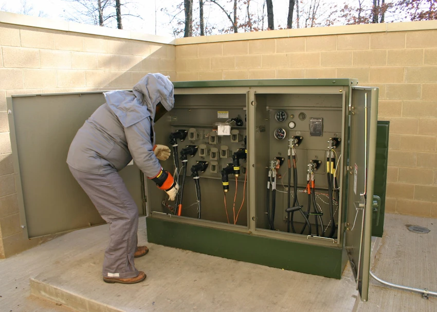
Including high voltage room, transformer room, low voltage room; the high voltage room is the power supply side, usually 35 kV or 10 kV incoming line, including high voltage busbar, circuit breaker or fuse, voltage transformer, lightning arrester, etc., in the transformer room They are all transformers, the main equipment of the box transformer. There are Low voltage busbars, low voltage circuit breakers, metering devices, lightning arresters, etc. in the low voltage room, and lines are drawn from the low voltage busbars to supply power to users.

The protection of box-type transformers is specifically designed to protect transformers. It is a high-tech power automation product developed and developed that integrates protection, monitoring, control, communication and other functions. It is an ideal electrical unit that constitutes an intelligent box-type transformer.
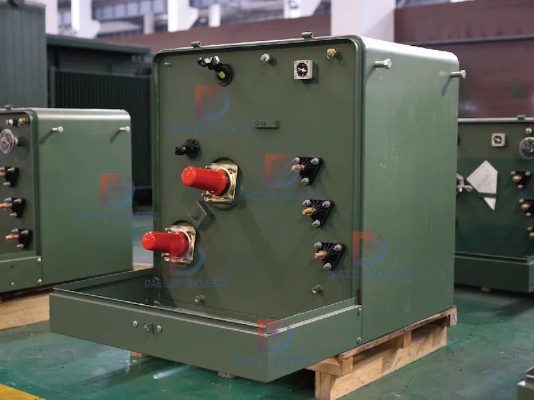
Box-type transformers are divided into European transformer and Pad-mounted. Pad-mounted is small in size, low in load capacity, low in power supply reliability, European style is larger, load capacity and power supply reliability are stronger than American style, in my country, European style is generally used Box change.
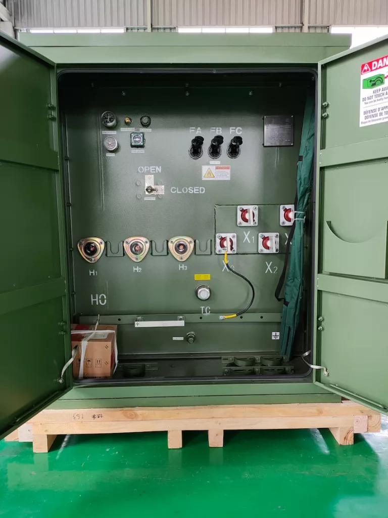
A combined transformer (also known as: Pad-mounted transformer) is a complete set of transformer and distribution equipment that combines transformer, load switch and protection device of high-voltage power receiving part, low-voltage power distribution device, low-voltage metering system and reactive power compensation device.
1. According to the insulation and heat dissipation medium: dry-type transformers, oil-immersed transformers, of which dry-type transformers are further divided into: SCB epoxy resin cast dry-type transformers and SGB10 non-encapsulated H-class insulated dry-type transformers.
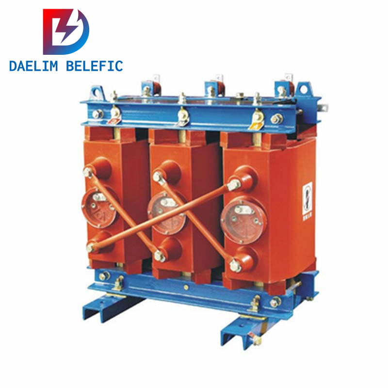
Transformers in which the core and windings are not immersed in insulating oil.
Comply with IEC726, GB6450, GB/T10228-1997 standards.
High Voltage(kV):6/6.3/10/10.5/11kV
Low Voltage(kV): 0.4 kV or other
Connection Symbol: Dyn11 Yyn0
Cooling Method: AN/AF
Rated Voltage: 10kV
Use oil as a medium to dissipate heat.
The circulation of insulating oil inside the transformer transfers the heat generated by the coil to the radiator (sheet) of the transformer for heat dissipation.
Comply with IEC60076, ANSI/IEEEC57.12.20,CSAC2.1-06, CSAC2.2-06 standards.
Ranging from 2400 to 34500 volts
Rated Power(kVA): 5 ~ 75
Cooling Method: AN/AF
Type: CSP
In terms of capacity, the current rated capacity of transformers in my country is calculated according to the R10 priority coefficient, which is calculated as a multiple of 10 to the power of 10, 50KVA, 80KVA, 100KVA, 125KVA, 160KVA, 200KVA, 250KVA, 315KVA, 400KVA, 500KVA, 630KVA , 800KVA, 1000KVA, 1250KVA, 1600KVA, 2000KVA, 2500KVA, 3150KVA, 4000KVA, 5000KVA, etc.
Some newly built commercial and residential communities are densely built and have a large installation load. The distance between distribution transformers in the community is short. Among the line losses of the distribution network in the area, the loss of distribution transformers accounts for a larger proportion.
The newly-built community has a low occupancy rate, a lighter load and a more scattered area. The distribution projects in the community generally install distribution transformers in one step according to the planned power load, which causes serious waste.
In addition, the peak load in summer is lighter than the load in winter, and there will be waste every winter. The traditional way to solve this problem is to replace it with a small-capacity transformer.
For example, a 630 kVA distribution transformer is replaced with a 315 kVA distribution transformer, and the product parameters of a transformer factory are used as an example for calculation. The parameters of SC3-630/10 distribution transformer are:
P10=1 800 W, P1K=5 270 W, I1n=909.3 A; The parameters of SC3-315/10 distribution transformer are P20=1 200 W, P2K=3 150 W, I2n=454.7 A. Substituting formula (5) into I″=260.2 A.
When the load current is less than 260.2 A, replacing the 630 kVA transformer with a 315 kVA transformer can reduce the loss of the transformer. If there are two adjacent 630 kVA distribution transformers, which are connected on the low-voltage side by a tie line, the load of the two distribution transformers will be supplied by one of them, and the other will be out of service for backup. According to formula (3), I’=375.8 A can be obtained.
If the tie line is very short, the loss of the tie line can be ignored. When the average load current of a single distribution transformer is less than 375.8 A, the above method can be used to reduce the loss of the transformer.
Suppose there are two adjacent 630 kVA distribution transformers, and compare the total losses of the two methods in the above example. If the average load current of a single distribution transformer is 200 A, and the two 315 kVA distribution transformers replace the 630 kVA distribution transformer with two 315 kVA distribution transformers, the loss of the two 315 kVA distribution transformers will be The sum is:
P2=2P20+2(I2/I22n) P2K=3619 W.
According to the latter method, a 630 kVA distribution transformer with 400 A load, its loss is: P1=P10+(I2/I21n)P1K=2820 W.
Obviously, if there are two adjacent distribution transformers, the latter method in the above example has a smaller total loss than the former method.
When the average load current of each distribution transformer is smaller, the loss reduction effect of the latter method in the above example is more significant. In practical applications, the low-voltage side tie line can be used to switch the operation mode by simply operating the low-voltage switch.
The replacement of transformers not only requires a lot of work, but also has a considerable number of spare transformers. The effect is not as good as the method of connecting wires, and it is not economically cost-effective. The tie-line method can be extended to multiple nearby transformers, and the critical load current can be obtained by simple calculations.
It is recommended to add a tie line on the low-voltage side in the design of the community distribution network. The wire diameter can be considered according to 1/3 to 1/2 of the rated load current of the distribution transformer. Flexible switching of the operating mode.
Unclear 10KV power transformer models include S11, and so on. The ability ranges from 50 to 1250kv. In regards to power transformers, I have actually never become aware of the prominent name 360. 10/0.4 kv This is the change proportion of a general transformer of 0.4 kv, which is generally 380v.
It must be the ability, today there is no 360KVA capability sector. The upper and reduced are 315KVA and 400KVA respectively. It is said that 400 usually refers to the distribution transformer of S11-M-400/ 10.
Table of Contents Selecting the right pad-mounted transformer requires careful consideration of several critical

The primary function of the pad mounted transformer is to serve as a critical distribution

A pad mounted transformer operates through electromagnetic induction, serving as a crucial distribution component that
When you need to find more than just existing transformers, Daelim’s Transformer Service Center can help you design and produce distribution transformers that meet your unique needs.
We have our own factory and a professional team of engineers, which can design and modify application requirements that meet all your conditions.
Download Resource
After filling in the contact information, you can download the PDF.