
How to Choose Pad Mounted Transformer?
Table of Contents Selecting the right pad-mounted transformer requires careful consideration of several critical
ELECTRIC, WITH AN EDGE
La diferencia de fase entre los potenciales de línea de devanado de alta y baja tensión de un transformador trifásico varía según el método de conexión del transformador de distribución trifásico.
La conexión de devanados de transformadores trifásicos no es solo una cuestión de formar un sistema de circuito, sino también una cuestión de armónicos en las cantidades electromagnéticas del transformador, así como problemas operativos como la operación en paralelo.
Por este motivo, es necesario identificar correctamente el grupo de acoplamiento del devanado trifásico.
El análisis de conexiones de transformadores trifásicos siempre ha sido un punto clave de énfasis y dificultad en el curso “Fundamentos de Máquinas Eléctricas y Arrastre”. El grupo de acoplamiento de devanados de transformadores trifásicos generalmente incluye dos aspectos del problema.
Primero, de acuerdo con el diagrama de cableado del devanado para dibujar el diagrama de fase correspondiente, determine el grupo de enlace.
El segundo es dibujar el diagrama de volumen de fase y el diagrama de cableado de acuerdo con el grupo de acoplamiento. El grupo de acoplamiento de transformadores trifásicos se usa comúnmente para describir la relación de fase entre el potencial de línea correspondiente en el lado de alto y bajo voltaje.
Devanado de alta y baja tensión para la conexión en estrella, con el símbolo “Y (o y)”, los tres primeros extremos del devanado A, B, C (o a, b, c) dirigidos hacia afuera, el extremo de X, Y , Z (o x, y, z) juntos para convertirse en el punto neutral, con N (o n) dicho.
Al hacer la conexión triangular, se utiliza el símbolo “D (o d)”, de modo que el primer extremo de una de las tres fases se conecta al extremo de la otra fase.
Debido a que el devanado trifásico se puede usar en diferentes conexiones, la tensión de línea en los devanados primario y secundario del transformador trifásico presenta diferencias de fase diferentes, por lo que la conexión del devanado del transformador se divide en varios grupos de conexión según la fase. relación entre el voltaje de la línea primaria y secundaria.
Hay muchos grupos de conexión posibles para transformadores trifásicos, pero por conveniencia de fabricación y operación en paralelo, el estándar de la industria especifica los siguientes cinco como grupos de conexión estándar: Y, yn, 0; Y, d11; SN, d11; Y, z11; D, z0. El símbolo z indica una conexión en zigzag.
El grupo de acoplamiento Y, yn, 0 tiene el lado secundario de la línea central de plomo, por lo que se convierte en un sistema trifásico de cuatro hilos, esta conexión se usa comúnmente en transformadores de distribución para energía e iluminación.
El grupo de acoplamiento Y, d11 se utiliza en líneas donde la tensión en el lado secundario supera los 400 V. El acoplamiento angular en el lado secundario del transformador facilita la operación.
YN, el grupo de acoplamiento d11 se utiliza principalmente en líneas de transmisión de alto voltaje; Los transformadores con acoplamiento en forma de z se utilizan en transformadores de distribución con un alto rendimiento de protección contra rayos.
Debido a que el sistema trifásico es más económico, eficiente y superior a la misma capacidad de los transformadores monofásicos, casi todos los países en los sistemas de energía del mundo utilizan el sistema trifásico, por lo que la aplicación de transformadores trifásicos está muy extendida. .
Los transformadores trifásicos operan en condiciones simétricas, el voltaje, la corriente y el flujo de cada fase son del mismo tamaño, y las fases se retrasan 120 ° a su vez, por lo que el análisis de los transformadores trifásicos se puede analizar siempre que un cierto se toma la fase.
Los transformadores trifásicos se pueden dividir en dos tipos según su estructura central: transformadores de grupo trifásico que consisten en tres transformadores monofásicos independientes, o llamados grupos de transformadores trifásicos.
El otro es un transformador tipo núcleo trifásico con un núcleo común a las tres fases.
Los transformadores trifásicos también están disponibles en tipos de núcleo y carcasa.
Las conexiones de los devanados de transformadores trifásicos no son solo una cuestión de composición del sistema de circuito, sino que también se relacionan con los armónicos en las cantidades electromagnéticas del transformador, así como con cuestiones operativas como la operación en paralelo.
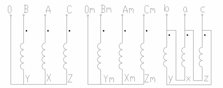
El devanado del transformador de potencia trifásico generalmente adopta dos tipos de acoplamiento, estrella y triángulo, y las regulaciones para la primera y última marca del devanado se muestran en la Tabla 1.
Nombre del devanado (bobina) | Arriba | Finaliza | punto neutro |
Devanado de alto voltaje (bobina) | A、B、C | X、Y、Z | N |
Devanado de baja tensión (bobina) | a、b、c | x、y、z | n |
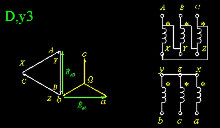
Las conexiones de transformadores trifásicos utilizan dos letras más un número de representación de reloj, donde la primera letra indica el método de conexión del lado original, con letras mayúsculas, la segunda letra indica el método de conexión del lado secundario, con letras minúsculas, Y o y indica una conexión en forma de estrella, D o d indica una conexión triangular, seguida de un número que indica la diferencia de fase del potencial de la línea lateral original y secundaria del transformador.
El último número indica la diferencia de fase del potencial eléctrico de línea lateral original y vice del transformador, es decir, el vector de potencial eléctrico de línea lateral original como la manecilla larga del reloj, y fijado en el “12”, vector de potencial eléctrico de línea lateral vice como la manecilla corta del reloj, el número de puntos de reloj que es el número del grupo de acoplamiento.
La diferencia de fase del potencial de la línea secundaria original solo es posible para un múltiplo entero de 30°.
Hay tres factores que afectan las conexiones del transformador trifásico: la forma en que se conectan los devanados original y secundario, el extremo del mismo nombre y el cambio de fase.
Hay dos tipos de conexiones de bobinado: estrella y triángulo.
El acoplamiento en estrella es la conexión de tres extremos de un devanado trifásico entre sí, con los tres primeros extremos saliendo y, a veces, con los tres extremos saliendo a través de la línea central.
La conexión triangular consiste en conectar el extremo de un devanado de fase con el primer extremo de otro devanado de fase, para formar un circuito cerrado, y luego salir del primer extremo, y la conexión triangular se divide en dos tipos: cis- enlace y enlace inverso.
La relación entre el potencial de línea y el potencial de fase del devanado es diferente dependiendo de la forma en que esté conectado el devanado.
Si la conexión del devanado se cambia de estrella a triángulo sin cambios en el potencial de fase, el potencial de línea se retrasará 30° con respecto al potencial de línea original.
Si la conexión del devanado se cambia de estrella a triángulo, el potencial de línea excederá el potencial de línea original en 30°.
Si la conexión del devanado se cambia de una conexión triangular a una conexión inversa triangular, el potencial de línea excederá el potencial de línea original en 60°.
A través de la relación anterior entre el cambio de fase del potencial eléctrico bajo diferentes métodos de conexión, no es difícil derivar el efecto del cambio en el método de conexión del transformador trifásico en el grupo de conexión.
En el caso de que no cambien otras condiciones, si el lado secundario del enlace de estrella cambia el paralelo triangular, el número de grupo de enlace más 1 (el voltaje de la línea del lado secundario retrasado 30 ° es equivalente a una rotación en el sentido de las agujas del reloj de la mano corta en el reloj un número de punto de reloj).
Si el lado secundario se cambia de una conexión en estrella a una conexión inversa triangular, el número de grupo de enlace se reduce en 1. Si el lado secundario se cambia de una conexión directa triangular a una conexión inversa triangular, el número de grupo de enlace se reduce en 2 .
Si los cambios anteriores ocurren en el lado original o en la dirección inversa, el número del grupo de vinculación se cambia en la dirección opuesta, es decir, más se convierte en menos y menos se convierte en más, mientras que la cantidad de cambio permanece igual.
El extremo epónimo del transformador se refiere a los dos terminales de los devanados original y vice en la misma columna del núcleo con la misma polaridad potencial en un instante determinado.
El extremo del mismo nombre depende de la dirección de bobinado de los dos bobinados en la misma columna central.
Cuando cambia la dirección de bobinado de uno de los bobinados, el extremo del mismo nombre cambiará, y viceversa, si cambia el extremo del mismo nombre, significa que la dirección de bobinado de uno de los dos bobinados en la misma columna central ha cambiado.
En otras palabras, cuando cambia el extremo del mismo nombre, la dirección del devanado de un devanado en el devanado secundario original cambia, el potencial de fase del devanado se invertirá y el potencial de línea correspondiente también se invertirá, y el potencial de línea tiene una fase cambio de 180° antes y después del cambio.
A través del análisis anterior, podemos obtener la ley de influencia del cambio del extremo del mismo nombre en el grupo de unión: para cada cambio del extremo del mismo nombre del transformador trifásico, el número del grupo de unión es más 6 o menos 6.
En un transformadors trifásico, los devanados que pertenecen a la misma fase en el devanado original y el devanado de vicio no están necesariamente instalados en la misma columna central, los devanados de origen y de vicio solo necesitan garantizar la relación de secuencia de fase respectiva en la línea, el original y los devanados de vicio en diferentes columnas centrales de este cambio de posición se denomina cambio de fase.
Si el devanado de fase U se desplaza al devanado de fase V, el devanado de fase V se desplaza al devanado de fase W y el devanado de fase W se desplaza al devanado de fase U, este cambio de fase se denomina cambio de fase. cambio de secuencia.
Por el contrario, si el devanado de fase U se cambia al devanado de fase W, el devanado de fase W se cambia al devanado de fase V y el devanado de fase V se cambia al devanado de fase U, el cambio de fase es llamada secuencia de fase inversa.
Cuando el devanado secundario del transformador trifásico se cambia una vez en la secuencia de fase, el potencial de fase en cada devanado de fase estará 120° retrasado con respecto al potencial de fase original, luego el potencial de línea en el devanado secundario también estará retrasado 120° de fase. cambio antes y después del cambio de fase, si este cambio de fase se refleja en el cambio del número del grupo de acoplamiento, es decir, más 4.
A través del análisis anterior, podemos obtener la ley del efecto del devanado que cambia al grupo de unión.
Cuando el devanado secundario se cambia una vez en secuencia de fase, el número de grupo de unión aumenta en 4, y cuando se cambia una vez en secuencia de fase inversa, el número de grupo de unión disminuye en 4.
Si el devanado original se cambia una vez en secuencia de fase, el número de grupo de unión se reducirá en 4, y si se cambia una vez en secuencia de fase inversa, el número de grupo de unión se incrementará en 4.
Después de dominar la ley de la conexión del transformador de distribución trifásico, el mismo extremo del nombre y el cambio de devanado al grupo de conexión, solo necesitamos recordar el diagrama de conexión de un grupo de conexión específico, luego podemos ver el método de conexión, el mismo nombre final, la situación de cambio de fase, y hacer una simple suma o resta al número de grupo del grupo de conexión específico de acuerdo con la ley de cambio. El número de grupo del grupo de enlace a identificar se puede obtener sumando o restando los números de acuerdo con la regla de cambio.
El grupo de acoplamiento específico puede elegir algunos fáciles de recordar, como Y, y0, el lado del vicio original de este grupo de acoplamiento es el mismo acoplamiento en estrella, el lado del vicio original del mismo devanado de fase en la misma columna central y el mismo nombre final es el mismo que el primer final.
El método de identificación rápida anterior no solo se puede utilizar para la identificación de la conexión del transformador de distribución trifásico, sino que también puede obtener rápidamente el diagrama de enlace correspondiente según el grupo de enlace.
El método específico es el siguiente.
En primer lugar, recuerde el diagrama de acoplamiento de un grupo de acoplamiento específico y realice los cambios correspondientes en el diagrama de acoplamiento del grupo de acoplamiento específico para obtener el diagrama de acoplamiento del grupo de acoplamiento objetivo.
en segundo lugar, para comparar la diferencia entre las letras de dos grupos de vinculación, para cambiar la vinculación del borde secundario original para que coincida con la correspondencia entre las letras y los patrones de vinculación, y para hacer una identificación rápida del nuevo grupo de vinculación después del cambio de la patrón de vinculación.
Finalmente, compare la diferencia entre el número de grupo entre el nuevo grupo de acoplamiento y el grupo de acoplamiento objetivo, convierta esta diferencia en una combinación de suma y resta en forma de 2, 4 y 6, y realice el ajuste correspondiente al devanado secundario original. de acuerdo con los cambios correspondientes a esta combinación de números para obtener el diagrama de acoplamiento del grupo de acoplamiento objetivo.
Por ejemplo, el diagrama de acoplamiento del grupo de acoplamiento Y, y0 se puede obtener rápidamente del diagrama de acoplamiento del grupo de acoplamiento Y, d5, donde los dos grupos de acoplamiento están conectados de diferentes maneras.
Primero, cambie el lado secundario de estrella a triángulo, agregue 1 al número del grupo de acoplamiento y obtenga el diagrama de acoplamiento de Y, d1, que difiere de Y, d5 en 4.
También es posible cambiar el lado del vicio de vinculación en estrella a vinculación inversa triangular para obtener el diagrama de vinculación de Y, d11, que difiere de Y, d11 a Y, d5 en el número de grupo de vinculación por 6, y el diagrama de vinculación de Y , d5 se puede obtener cambiando el mismo nombre una vez.
Se puede observar que a un mismo grupo de ligamiento le corresponde el mismo modo de ligamiento no es único.
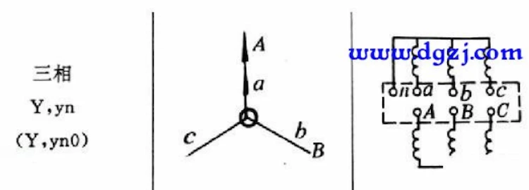
1, la conexión del transformador Y, yn0 del devanado interno del lado primario está conectado a la estrella, el lado secundario también está conectado a la estrella, el lado primario y secundario del voltaje de línea en la misma fase.
El factor de llenado del cable de bobinado es grande, la resistencia mecánica es alta y el consumo de aislamiento es bajo, por lo que el sistema trifásico de cuatro cables se puede usar para suministrar energía de bajo voltaje y cargas de iluminación.
2, grupo de acoplamiento Y,yn0 de transformadores de distribución, el devanado original no puede pasar la corriente de excitación en el tercer componente armónico, por lo que el flujo principal se convierte en una onda superior plana, es decir, en el flujo principal contiene el tercer componente armónico.
El tercer componente de flujo armónico en el núcleo no puede formar un circuito, solo a través del tanque de aceite y otras partes de hierro como un circuito, lo que aumenta la resistencia magnética, por lo que la pérdida aumenta bruscamente, lo que resulta en un aumento de la temperatura del calor local, eficiencia operativa disminuido
3, Y, transformador de grupo trifásico de cableado yn0 no puede tomar carga monofásica; El transformador de corazón trifásico de cableado Y, yn0 puede tomar una pequeña carga monofásica.
Conexión del transformador Y,yn0 para controlar el lado secundario de la simetría de carga trifásica. Grupo de conexión general Y, yn0 de la carga secundaria del transformador de distribución para carga mixta de energía e iluminación, es decir, en una red de distribución, tanto de carga trifásica como mixta con carga monofásica, esta situación es muy fácil de aparecer trifásica. asimetría de carga de fase.
Cuando la carga trifásica no es simétrica, habrá corriente de secuencia cero en el devanado de bajo voltaje.
El flujo de secuencia cero inducido por el flujo de secuencia cero se superpone al voltaje de cada fase, lo que da como resultado un desplazamiento del punto neutro del voltaje trifásico.
Como resultado, el voltaje de la fase fuertemente cargada cae y el voltaje de la fase ligeramente cargada sube, lo cual es perjudicial para el lado de bajo voltaje del aparato. El tamaño del flujo de secuencia cero depende del tamaño de la corriente de secuencia cero.
Por lo tanto, las normas pertinentes estipulan que la corriente de la línea neutra secundaria de la conexión del transformador Y,yn0 no debe exceder el 25 % de la corriente nominal del devanado de baja tensión. Cuando la corriente de la línea neutra no supera este valor, la tensión de compensación en el punto neutro es aproximadamente el 5% de la tensión de fase, el efecto sobre la tensión trifásica no es significativo y aún puede considerarse básicamente simétrico.
4. Conexión del transformador Y, yn0 Cuando el fusible de alto voltaje fusiona una fase, habrá un voltaje de fase de cero, las otras dos fases del voltaje no cambiaron, puede hacer que el rango de interrupción se reduzca a 1/3.
Esta situación no afecta a las cargas de alumbrado con alimentación monofásica en el lado de baja tensión. Si el lado de bajo voltaje es una fuente de alimentación trifásica, generalmente configurada con protección de pérdida de fase, no hará que la carga de energía se quede fuera de fase y se queme.
5. Como la resistencia del aislamiento del devanado primario de la conexión del transformador Y,yn0 es ligeramente inferior a la de la conexión del transformador D,yn11, el coste de fabricación es ligeramente inferior al de la conexión del transformador D,yn11.
Por lo tanto, en los sistemas TN y TT, la corriente de línea neutra causada por una carga desequilibrada monofásica no supera el 25 % de la corriente nominal del devanado de baja tensión, y la corriente de una fase no supera el valor nominal a plena carga. , todavía se puede utilizar.
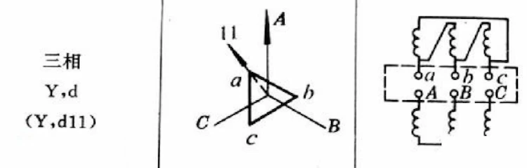
1、El devanado interno de la conexión del transformador Y,d11 está conectado como una estrella en el lado primario y un triángulo en el lado secundario, con el voltaje de la línea secundaria rezagado con respecto al voltaje de la línea primaria en 3300.
2, la conexión del transformador Y, d11 puede hacer circular la corriente del tercer armónico, eliminando el voltaje del tercer armónico. El punto neutro no está conectado, comúnmente utilizado en el punto neutro no está muerto, el voltaje secundario es superior a 400 V en el transformador reductor mediano y grande.
3, conexión del transformador Y, d11 en funcionamiento normal, el lado secundario tiene una buena forma de onda sinusoidal, alta calidad de potencia, la conexión del transformador Y, d11 con carga no está limitada.
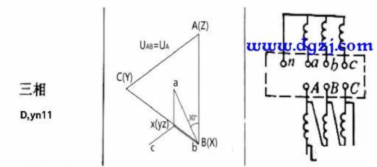
1、El devanado interno de la conexión del transformador D,yn11 está conectado como un triángulo en el lado primario y una estrella en el lado secundario, con el voltaje de la línea secundaria rezagado con respecto al voltaje de la línea primaria 3300.
2, la conexión del transformador D, yn11 tiene una alta calidad de voltaje de salida, el punto neutral no se desplaza, un buen rendimiento de protección contra rayos, etc.
Cuando la carga trifásica en el lado de bajo voltaje está desequilibrada, el potencial magnético de secuencia cero total y el potencial de tercer armónico en cada columna del núcleo son casi iguales a cero porque la corriente de secuencia cero y la corriente de tercer armónico pueden circular en el circuito cerrado del devanado de alto voltaje, por lo que el potencial neutral de bajo voltaje no se desvía y el voltaje de cada fase es de alta calidad.
Del mismo modo, como la corriente del rayo también puede circular en el circuito cerrado del devanado de alto voltaje, el potencial magnético total de la corriente del rayo en cada columna del núcleo es casi igual a cero, lo que elimina la sobretensión positiva y negativa, por lo que el rendimiento de la protección contra rayos es bueno.
Sin embargo, existe el problema de la operación de fase no completa, que se puede adoptar agregando un dispositivo de protección de bajo voltaje al interruptor principal de bajo voltaje.
3, conexión de transformador D,yn11, su corriente de excitación armónica 3n (n para entero positivo) en su cableado triangular del devanado primario para formar un bucle, no inyectado en la red pública, que es más propicio para suprimir corrientes armónicas altas que el devanado primario conectado al cableado en forma de estrella del grupo de conexión Y,yn0.
4, D, transformador de distribución del grupo de conexión yn11, el flujo principal se vuelve sinusoidal, el potencial de inducción en el devanado secundario también es sinusoidal, lo que mejora la calidad de la forma de onda del voltaje de salida, es decir, mejora la calidad de la fuente de alimentación.
5, D, transformador de cableado yn11 que Y, la impedancia de secuencia cero del transformador de cableado yn0 es mucho más pequeña, conducente a la eliminación de fallas de cortocircuito de puesta a tierra monofásica.
6, cuando se conecta a una carga desequilibrada monofásica, los transformadores de cableado Y, yn0 requieren que la corriente de línea neutra no supere el 25% de la corriente nominal del devanado de bajo voltaje, lo que limita la capacidad de la carga monofásica, lo que afecta la totalidad uso de la capacidad del equipo del transformador.
La conexión del transformador D,yn11 permite que la corriente de línea neutra alcance más del 75% de la corriente de fase, y su capacidad para soportar corrientes monofásicas desequilibradas es mucho mayor que la de la conexión del transformador Y,yn0. conexión.
Esto hace que sea aún más necesario promover el uso de la conexión del transformador Dyn11 en los sistemas de suministro de energía modernos donde las cargas monofásicas están aumentando dramáticamente.
Download Resource
Table of Contents Selecting the right pad-mounted transformer requires careful consideration of several critical

The primary function of the pad mounted transformer is to serve as a critical distribution

A pad mounted transformer operates through electromagnetic induction, serving as a crucial distribution component that
After filling in the contact information, you can download the PDF.