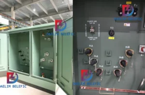
How to Choose Pad Mounted Transformer?
Table of Contents Selecting the right pad-mounted transformer requires careful consideration of several critical factors, as these ground-mounted distribution transformers play a vital role
ELECTRIC, WITH AN EDGE
As an important power conversion device in the power system, the 10 kv transformers occupies an important position in the power supply system.
As the equipment with the longest working hours in the substation, transformers will have many abnormal conditions and failures during operation.
These faults will directly affect the safety and reliability of power grid operation, so it is very important to conduct state inspection and troubleshooting of transformers.
This paper analyzes the condition maintenance and related faults of 10kV transformers.
With the rapid development of the economy and industry, there are higher requirements for the reliability of grid operation and power quality.
The transformer, as the conversion device of the electric energy voltage level, has an important influence on the safe operation of the power grid.
The 10kV transformer is an important part of the substation, and reasonable maintenance can improve the safety and reliability of the grid operation.
Transformer state maintenance refers to preventive maintenance based on the state information provided by equipment monitoring, diagnosis, and evaluation.
An overhaul is an act that integrates all technologies and management of power transmission and transformation equipment, including the supervision and management required to maintain or restore it to the required functional state.
The condition maintenance of the transformer is based on a scientific and reasonable analysis method, which integrates the status of various detection and analysis equipment.
At the same time, based on the evaluation results, a comprehensive maintenance method for the maintenance strategy is finally obtained.
This kind of maintenance method can not only save costs, extend the annual inspection cycle of the transformer, but also improve the reliability of the transformer operation.
Compared with the traditional regular inspection, the 10kV transformer status maintenance can monitor the transformer running status in real-time for 24 hours.
At the same time, this transformer detection method ensures the necessity of each detection work, avoids the waste of manpower and material resources, and saves related resources and time.
The use of this inspection method also improves the reliability of the 10kV transformer operation.
At this stage, 10kV transformer maintenance requires a lot of manpower and material resources, but the maintenance effect is only average.
According to statistics from the Electric Power Research Institute (EPRI) and the Industrial Power Equipment Maintenance Company (CSI), the implementation of proper state maintenance in the power system can increase the availability of transformers by 2% to 10%, and save maintenance costs by 25% to 30%. Extend transformer life by 10%~15%.
In addition, it is necessary to conduct pre-tests for substation maintenance and frequent bus inversion operations before taking the status overhaul of the substation.
On average, there are more than one misoperation accidents caused by this every year, and no misoperation accident has occurred since the state maintenance was taken.
In the annual pre-test, the defect rate of 10kV—110 kV equipment is significantly reduced, and the defect rate is only one-thousandth to two-thousandths.
In the operation of the substation, the main purpose of the selection and application of station transformers is to ensure that the output voltages of the station transformers and backup transformers in the substation connected to the grid are consistent, so as to provide a guarantee for the safe and stable operation of the power system.
Combined with the current transformer types used in power system substation stations, Dyn and Yyn connection types are the main ones. And the zero-sequence impedance of the transformer of the first connection type is much lower than that of the second connection type.
Among them, the single-phase short-circuit current in the operation of the transformer will increase and change, and the difference between the three-phase short-circuit current and the three-phase short-circuit current will be significantly reduced.
This means that in the station transformer system using the first connection type, the protection action sensitivity of the system protection equipment under the problem of single-phase short-circuit faults is greatly improved, and at the same time, the system protection equipment and the circuit feeder line cross-section selection and coordination are greater.
In addition, the simplified setting and application of the system protection structure and form can also be realized, without the need for separate settings and application of single-phase short-circuit protection. In the high-voltage side, overcurrent protection of the power system and the low-voltage side single-phase short-circuit protection, both have more advantages.
Dyn type connection transformer equipment, its internal delta winding arrangement creates a current path for the third harmonic current or zero sequences current in the transformer connection line, and at the same time makes the phase voltage in the line closer to the sine wave The voltage change form has a more prominent effect and effect on the improvement of the line voltage waveform quality.
In addition, in this type of connection type transformer equipment, if there is a three-phase load imbalance on the low-voltage side of the transformer connection line, the floating displacement of the low-voltage side neutral point in the transformer equipment will not change, thereby supplying power to the grid. The stability of it has a greater guarantee.
Therefore, in actual design and application, D, yn type connection transformers are the main choice for substation station transformers.
In addition, the impedance calculation of the D, yn type connecting transformer in the operation of the substation is generally determined based on the current-carrying capacity of the low-voltage electrical appliances in the substation system under short-circuit faults. According to this situation, the impedance of the transformer is used in the substation station. In the selection and design applications, ordinary transformers designed with standard impedance are generally used as transformer equipment for substation stations for selection and application.
Take a transformer for a 220kv substation station as an example. The transformer is a dry-type transformer with forced air cooling and a protective enclosure.
After determining its technical parameters, including the operating frequency of the transformer, no-load current, insulation grade, withstand voltage, connection method, operating environment, etc., the capacity of the transformer can be calculated according to the comprehensive situation of each load in the substation Determine, and select the application in the design of the substation.
Transformer faults are divided into external faults and internal faults.
External faults generally refer to faults that occur outside the transformer, such as rupture of the insulating bushing.
Internal faults refer to faults that occur inside the transformer, such as short-circuits between transformer windings, short-circuits between winding coils, and so on.
Secondly, because the production process of the transformer is unreasonable, the production process is unqualified, and the windings cannot be tightly pressed together, the windings of the transformer will be deformed during the working process and the insulation will be damaged.
In addition, the contact time between transformer insulating oil and air will cause acidification of the oil and reduce the insulation effect. If moisture is mixed into the transformer insulating oil, the insulating oil will deteriorate.
Faults such as the grounding of the transformer winding, the short circuit between the windings of the winding, the disconnection of the winding, and the open welding of the winding outlet joints are all faults of the transformer winding.
Many reasons can cause the above-mentioned types of faults in the transformer windings.
For example, if sundries fall into the windings during the operation of the transformer, the temperature of the windings of the transformer will rise, resulting in aging or damage to the insulation, leaving defects.
Best Epoxy-resin Three Phase Dry Type Tansformer Manufacturer
The insulation damage of the clamping screw of the transformer iron wheel or the core screw of the iron core post will cause the iron core of the transformer to fail.
When the iron core of a 10kV transformer fails, it will short-circuit the iron sheet and screw of the transformer.
As a result, a circulating flow between the iron sheet and the screw generates a large amount of heat.
Eventually, the laminated insulating medium in the iron core melts and is damaged, which leads to the deterioration of the insulating medium.
If it has been determined that the iron core is faulty during the operation of the transformer, the fault needs to be eliminated in time.
During fault detection, the resistance between the windings of each phase of the transformer should first be measured. If the resistance of the DC resistance between the windings is very different, it means that it is a fault between the windings.
Then inspect and measure the appearance of the transformer core, and measure its insulation resistance. If the damage is very serious, the core needs to be replaced.
The main protection of transformers generally adopts gas protection, which is divided into light gas protection and heavy gas protection. The gas protection will also have some faults in the working process.
The following introduces the causes of two kinds of gas protection malfunctions and the corresponding treatment measures.
Electric Pole Transformer | Single Phase Transformer | Daelim
When the protection circuit inside the transformer fails, water enters the transformer or the internal components are not firmly fixed, the fault will occur.
Once a light gas failure signal appears, gas samples should be collected at the Buchholz relay and sent to the test unit for analysis.
The following introduces the causes of two kinds of gas protection malfunctions and the corresponding treatment measures.
Three-Winding Transformer | Three-Phase Transformer | Daelim
Under normal circumstances, only serious faults inside the transformer will cause the transformer oil to decompose and produce a large amount of gas within a period.
When the transformer has heavy gas protection action, the spare transformer should be put into use immediately.
At the same time, the faulty transformer shall be inspected and repaired.
The total capacity of a 10kV substation is 30MVA, with 10kV incoming lines two times, and 6kV for six times.
Among them, the 10kV and 6kV bus circuits adopt a single bus segmented connection.
Station #2 found that the capacity of the 10kV bushing exceeded the standard during the power outage experiment of the main transformer.
So notify the manufacturer to replace the casing. 80 kg of transformer oil was injected into the transformer when the bushing was replaced.
After the transformer is put into operation again, the chromatographic tracking method is used to analyze the insulating oil by the regulations.
The analysis results showed that the content of total hydrocarbons and hydrogen in transformer oil increased abnormally.
The measures taken are to take multiple samples for analysis and strengthen the monitoring of equipment conditions.
Analyze the operating status of the transformer by using state detection techniques such as chromatographic analysis, infrared temperature measurement, and iron core grounding test, and finally determine the cause of the fault.
First, perform chromatographic analysis on the transformer oil. After detection and analysis, it is found that ethylene is the main component, so it can be judged that there is overheating inside the transformer.
Then, the core ground current test was carried out. The test current was 62mA and did not exceed the specified upper limit of 100mA.
Therefore, there is no overheating of the iron core. Based on the above two sets of test data, it can be known that the fault of the transformer should be the poor connection of the loop.
Then test the voltage regulator switch on the 10kV side and the connection points of the outlet and conductive rods on the 10kV and 6kV sides.
After draining the transformer oil, check the voltage regulator switch on the 10kV side, and found that the three-phase contacts of the transformer have varying degrees of burns.
The equipment was powered off and the 10kV DC resistance test was carried out. After the test, the three-phase unbalance degree was 52%.
Therefore, combining all the above test results, it can be known that the fault area is near the voltage regulating switch on the 10kV side.
Disassembling and analyzing the pressure regulating switch on the 10kV side, it is found that the spring pressure of the contact part of the pressure regulating switch is not enough.
This will cause poor contact and heat the contact area.
In addition, the quality of the materials used in the voltage regulator switch is not good enough, and the design process cannot meet the requirements.
For the above reasons, manufacturers are required to replace related components and take pre-test measures for another transformer in time.
After the transformer is repaired, oil is taken from the transformer three times a week, and status inspection work such as tracking and analysis of the oil situation is carried out to prevent similar failures from recurring.
The transformer is one of the most important pieces of substation equipment.
Its safe operation will directly affect the safe operation of the power grid.
Although the transformer itself has many protection measures, due to the complex internal structure of the transformer, the demand for electric energy from the power grid changes at all times, resulting in various abnormal phenomena during the operation of the transformer, and the failure rate of the transformer is relatively high.
Traditional transformer maintenance methods can no longer meet the requirements for equipment reliability at this stage.
This article analyzes the 10kV transformer condition maintenance and related faults with examples. The transformer condition maintenance can not only save costs but also effectively improve the reliability of equipment operation, and ensure the safe operation of the power grid.
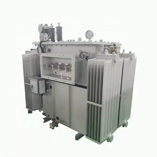
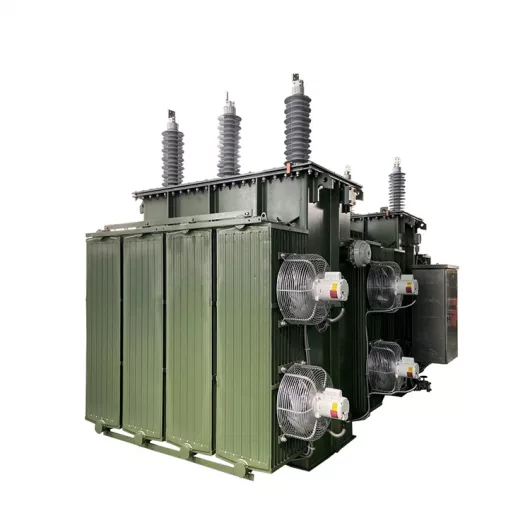
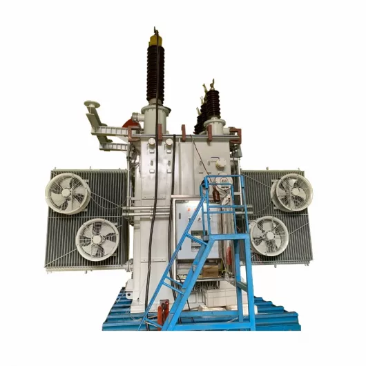
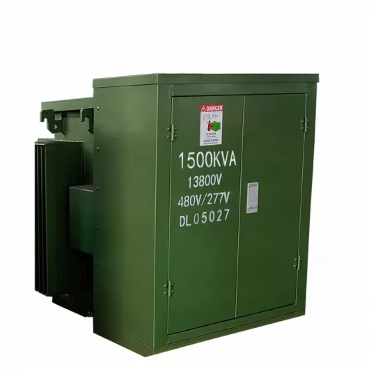

Table of Contents Selecting the right pad-mounted transformer requires careful consideration of several critical factors, as these ground-mounted distribution transformers play a vital role
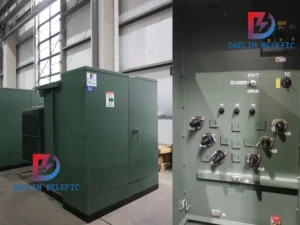
The primary function of the pad mounted transformer is to serve as a critical distribution transformer that steps down higher primary voltage from utility distribution
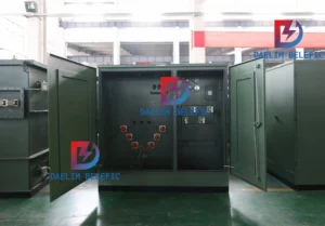
A pad mounted transformer operates through electromagnetic induction, serving as a crucial distribution component that converts high voltage electricity to lower, usable voltages for residential
When looking for the best pad-mounted transformer manufacturer, it’s important to find industry leaders known for reliability and innovative solutions. Pad-mounted transformers are essential in
After filling in the contact information, you can download the PDF.