How to Choose Pad Mounted Transformer?
Table of Contents Selecting the right pad-mounted transformer requires careful consideration of several critical
ELECTRIC, WITH AN EDGE
In the future, the energy industry will continue to develop in a low-carbon direction, and photovoltaic power generation is a key part of renewable and clean energy generation. In order to reduce the cost of electricity for photovoltaic plants and increase the power generation capacity, we have conducted a study by consulting relevant information, introduced the capacity allocation ratio, analysed the technical issues related to the capacity retrofit of photovoltaic plants, and explored the measures for the capacity retrofit of photovoltaic plants, aiming to increase the actual power generation capacity of photovoltaic power plants with the help of capacity retrofit engineering technology. The aim is to improve the actual power generation capacity of photovoltaic power plants by means of capacity retrofitting engineering.
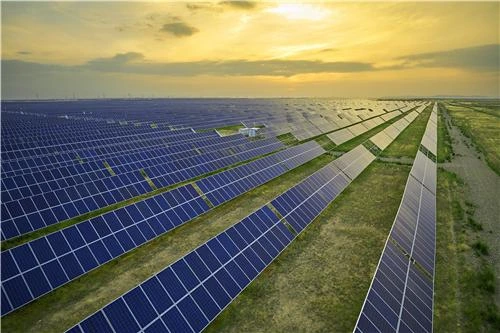
The construction of the photovoltaic industry is an important part of the energy reform process. The majority of early pv plants have been in operation for more than 5a, and most photovoltaic power plants are no longer as efficient as they used to be due to old equipment and diminishing module power. This is an inevitable trend to improve the economic efficiency of photovoltaic plants.
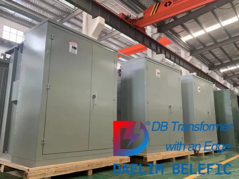
Choosing Daelim as the supplier of transformers for your PV plant ensures that you receive high-quality, safe, and reliable products that meet international standards such as IEC 60076, GB 6451, AS NZS 60076, CSAC88-16, ANSI/IEEE C57.12.00, and GOST R 52719. Compliance with these standards helps to ensure the safe operation and reliable performance of the transformers, reducing the risk of accidents and downtime in your PV plant. Additionally, Daelim’s commitment to providing excellent customer service and customized solutions can help to meet your specific needs and requirements, ensuring the success and efficiency of your PV plant.
The capacity ratio in photovoltaic plants is the ratio between the rated system capacity and the capacity of the installed modules. When the ratio exceeds 1:1, the actual capacity of the PV modules is greater than and equal to the actual capacity of the inverter. Increasing the over-matching ratio will result in a reduction in the number of strings, thus accelerating the reduction of DC cables and reducing the actual cost of AC cables and the specific number of inverters, thereby increasing the overall system power output.
The reasons for increasing the capacity ratio are as follows: a) There is a gap between the actual power output of the PV modules and the standard power. The standard power is usually measured at 25°C in a standard environment, with a radiation irradiance of 1200 W/m2 and a spectral distribution of 1.5.
However, there are large differences in radiant illuminance in different regions, so the difference between the output power of the module and the theoretical value is often large.
b) There are PV system losses. Usually PV systems generate two types of losses in the process of power generation.
(a) Mismatch losses. The differences between different strings, either as individual modules or in the formation of different PV arrays, can lead to mismatching of the output and thus to mismatching losses. (b) Inverter losses.
These are losses in the inverter itself, e.g. losses in the conversion of current during the operation of the inverter.
According to most photovoltaic plant data, the inverter losses in the pv plant itself are typically 15% of the DC losses, and this does not include the actual losses in other lines and equipment.
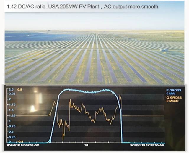
The importance of increasing the capacity ratio is that it
a) It helps to match the energy storage system perfectly and to achieve a stable power output.
b) To compensate effectively for the lack of light, reduce the power drop caused by different factors and promote the stable power output of the pv plant.
c) Improving the actual power of the components can improve the start-up efficiency of the inverter to a certain extent, resulting in an extended power generation time.
d) further improve the efficiency of the use of box transformers, inverters and other related equipment, reducing the input costs of related facilities and equipment, thereby reducing the operating costs of the pv plant.
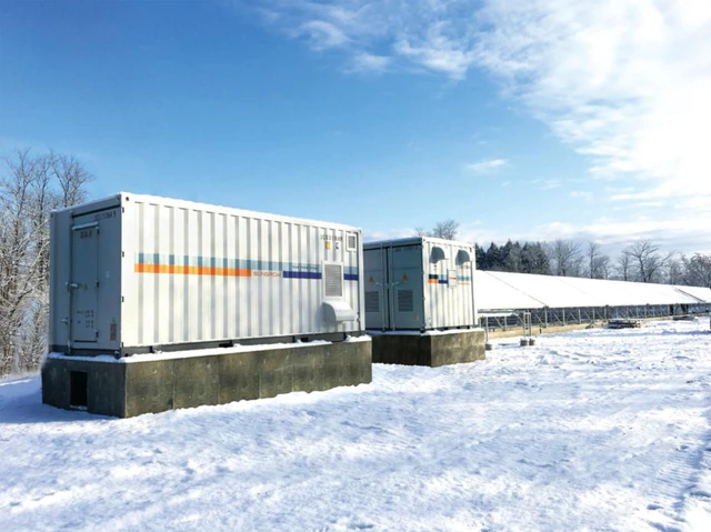
The conversion of a pv plant requires an in-depth analysis of the actual access to the pv plant, including the specific situation of the capacity increase arrangement and electrical equipment, such as the actual access to inverters, distribution cabinets and current convergence boxes.
Usually, pv plants are left with unused land in the booster area, near the fence, etc., which is used as space for additional capacity. Based on the back-end data of the sink box and the actual voltage and current output of the pv plant, effective screening of the strings is carried out and the array supports are partially replaced in this way. Attention is also paid to the verification of the original electrical equipment system, such as the parameters of the circuit breakers and DC quantities, the output and input parameters of the equipment such as the busbars and inverters, etc.
In addition, before carrying out the pv plant capacity increase transformation, it is also necessary to fully consider whether the strings can be combined after dismantling, and try to incorporate the newly capacitated arrays into the same square array, this process needs to account for the specific costs, if the dismantling is difficult, the solution of integrating the strings with the original sub-array system can be used.
The capacitance increase transformation poses a number of problems, as follows.
a) Mixing between old and new components can lead to problems of mismatch losses due to different performance. Generally, strings of different brands are not mixed into the inverter. pv plant has a limited practical layout area, which can lead to power mismatch between the original string and the capacitor string. However, it is worth noting that the use of PV sub arrays for mixing will also not maximise the performance and effectiveness of the strings and will result in a loss of power from the photovoltaic power plant.
There is a certain voltage difference between the original string and the new string, which will reduce the voltage output of the new module to varying degrees, and the pv plant inverter will become a centralised inverter with only one way. The mixing of the two strings with a large difference will prevent the power point limits from being clearly located, affecting the tracking of the power point and losing power generation.
b) Active and compensated over-matching brings about the problem of discarded light loss while increasing power generation. Generally the original pv plant will set the capacity allocation ratio between 1.1 and 1.5, while the actual capacity allocation ratio in most areas is basically between 1.5 and 1.9. In order to improve the efficiency, the active over-allocation scheme is chosen to complete the pv plant’s capacity increase and renovation work under the condition of capacity increase, which can further increase the capacity of the square array and thus promote the overall increase of the pv plant’s power generation capacity.
The implementation of the over-allocation measures requires the investor to verify the maximum power data of the system and to adjust the capacity increase design to the maximum power of the inverter. If the system data is insufficient, an analysis based on the overall efficiency of the pv plant is required.
For example, after many years of use, the actual power of a 500kW central inverter will decay to 400kW, while the actual overcapacity of the inverter is 1.1 times the original capacity, resulting in a power-limiting situation for the inverter. If the loss of the new strings is not taken into account, it is equivalent to 150kW of access capacity remaining in the array, but the new strings are generally not optimised due to mixed connections, resulting in a loss of some of the additional capacity.
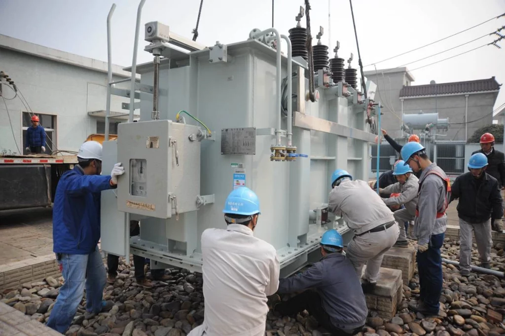
In the current system optimisation process for photovoltaic plants, it is important to consider increasing the return on investment of the pv plant while effectively reducing investment costs. The overmatching design can make the pv plant more economically efficient, reduce electricity costs and increase the utilisation rate, which is one of the effective ways to achieve capacity increase and renovation of photovoltaic power plants.
Reasonable and scientific inverters are the basic configuration for PV systems to achieve large-scale overmatching. The actual capacity of the PV modules is generally smaller than the standard rated capacity of the inverter during the period of no over-allocation, when the inverter is operating at a light load.
Normally, compensated over-matching enables the energy of the PV modules to be boosted, thereby compensating for the lost system energy and enabling the operating inverter to achieve full power.
Active over-allocation is to actively extend the inverter’s load running time on the basis of compensation, increasing the actual capacity of the modules and achieving a dynamic balance between power generation revenue and input costs.
The specific measures for the capacity increase transformation are as follows.
a) Effective capacity increase on the DC side. In accordance with the actual installed capacity of the pv plant, when the DC side meets the relevant installation requirements of the over-allocation design, effective capacity increase on the DC side is carried out, which can increase the actual capacity of the modules to a certain extent.
b) Effective capacity reduction on the AC side. In accordance with the specific capacity of the pv plant, effective measures are taken to reduce the communication-related capacity configuration, reduce the inverter capacity and reduce the corresponding investment.
c) Combination of AC measurement and DC side. The capacity of the pv plant is calculated according to the AC measurement. The DC side cannot be fitted with over-allocated components due to lack of land, so it is necessary to determine the land area and then adjust the relevant capacity, and then select the best capacity ratio according to the different conditions of light resources, so that the actual capacity of the AC measurement can be further reduced, and ultimately reduce the investment cost.
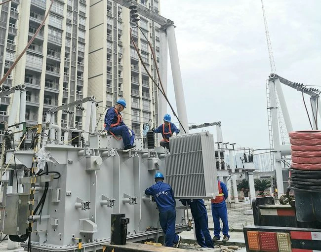
At the present stage, photovoltaic plants basically use overmatching design solutions, with the capacity ratio generally being more than 1.5 times the original, and some pv plants even up to 2 times and more. In many countries, overmatching is also being promoted. In the context of over-matching design, the following points should be noted in the selection of inverters.
a) The voltage withstand efficiency of the inverter should be maintained at a certain strength.
The use of overmatching designs in photovoltaic plants generally minimises system losses, but there is still the problem of the actual power being higher than the standard power of the inverter, causing the inverter to overload and making it reach the load protection point.
Therefore, the inverter needs to have a strong voltage withstanding efficiency to ensure to a certain extent that the output power is balanced with the rated power, so that the inverter can be used at its optimum efficiency.
b) The inverter should be selected for its strong heat dissipation capability.
The realisation of system overmatching tends to prolong the actual full load running time of the inverter. Especially in some pv plants such as mountainous areas and rooftops where the heat dissipation conditions are poor and the ambient temperature is relatively high, the inverter will generally have an overload running situation. In summer some concrete roofs or colour steel tiles are affected by thermal radiation and the ambient temperature is more than 10°C higher than the pv plant, which requires the inverter to have an extremely strong heat dissipation capability.
c) The inverter has to meet the specific access requirements on the DC side.
The capacity of the components is lower than the AC power of the equipment when the inverter has a DC excess on the input side. At this point, external factors such as dust shielding should be taken into account, and the actual current transmission power of the inverter should be reduced by about 10% in combination with the cable loss and component attenuation, which will leave the electrical system, transformer and inverter in a light-load operation for a long time.
The capacity increase design enables the actual efficiency of the box transformer and inverter to be effectively increased, while reducing the actual cost of the photovoltaic plants and reducing the amount of investment in the relevant facilities and equipment. In the case of over-provisioning, the AC line losses are generally not taken into account, and the load carrying capacity of the box-type transformer should be 1.1 times higher than before.
The capacity ratio has a certain degree of influence on the actual power of the inverter. The inverter operating hours are proportional to the capacity ratio and therefore the capacity on the DC side will change accordingly. pv plant actual utilisation hours will gradually decrease from the first year onwards.
At a capacity ratio of 1.5:1, the number of hours utilised by the pv plant does not change much, and when this is exceeded, the number of hours utilised decreases significantly. And when the value of the capacitance to capacity ratio decreases, the number of hours utilised in the first year tends to decrease significantly.
Different capacity ratios will increase the length of the DC cable, therefore, the actual situation of the capacity ratio and DC line loss needs to be followed to increase the power generation of the pv plant appropriately without increasing the input cost of the AC equipment, so as to maximise the value and role of the AC equipment.
The impact of different over-allocation designs on the cost of electricity is as follows: a) Impact on the cost of electricity on the AC side. If the capacity on the AC side is fixed, the capacity increase can appropriately reduce the cost of AC cables, inverters and box transformers. It will also reduce the variation of the actual power of the photovoltaic plants, achieve a stable and smooth pv plant output, improve the overall friendliness of the grid and reduce the cost of electricity consumption to a certain extent.
b) Impact on DC-side power cost. Based on the cost and mechanism of photovoltaic power generation, only capacity increase can effectively increase the actual capacity of the DC side of the photovoltaic power plant. As the proportion of capacity increase increases, the actual impact of module degradation, weather and temperature factors on the pv plant decreases.
If the energy storage system is subsequently added, the storage system can be used as a support power source for dispatching work, providing sufficient power for the DC side, further increasing the utilisation rate of transmission lines, booster stations and other equipment, reducing some of the utility costs and promoting an effective reduction in the cost of electricity per unit and the actual cost of the project.
Component attenuation affects the capacity ratio of pv plants to a certain extent. Currently, the base life of photovoltaic plants is generally 25a, and as PV materials decay and age, the pv plant capacity ratio tends to decrease year by year. pv plant actual use time and capacity ratio are linearly related, the longer the time, the smaller the capacity ratio.
However, if the pv plant’s initial capacity ratio is higher than the base theoretical capacity ratio, even if it decreases over time, the annual utilisation hours will increase further as the inverter power decreases. Although the rate of module decay is faster than the actual increase in power generation, the capacity increase can control to some extent the decrease in power generation due to module decay.
Before the introduction of the relevant standards, the capacity allocation ratio was generally 1:1, and the actual industry cannot be greater than 1:1.15, while the installed capacity of inverters previously only reached about 0.9 times the standard. After the release of the capacity allocation ratio, the standard configuration of inverters is 1:1, and the average ratio of component overmatching is 1:1.12, which means that the demand for components and the actual demand for inverters will increase by about 20%. In addition, scientific and reasonable over-matching can, to a certain extent, promote project efficiency, reduce the cost of electricity, and help photovoltaic power plants in different regions to achieve economic parity in power generation.
With the continuous exploration of photovoltaic power generation, more and more old PV plants will be retrofitted with additional capacity in the future. Generally speaking, for the purpose of retrofitting pv plants for efficiency purposes, the design plan can be adjusted from different angles, starting from the electrical equipment parameters and idle space of the original pv plant, and taking into account the input cost of the project, to determine whether the retrofitting should be carried out directly or in the form of disassembly and replacement.
In the case of mixed photovoltaic plants, there are also options to analyse active and compensatory over-allocation, and to analyse the actual losses, so that a scientific and effective solution for capacity increase and renovation can be developed.
Download Resource

Table of Contents Selecting the right pad-mounted transformer requires careful consideration of several critical
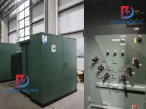
The primary function of the pad mounted transformer is to serve as a critical distribution
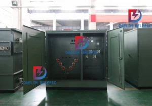
A pad mounted transformer operates through electromagnetic induction, serving as a crucial distribution component that
After filling in the contact information, you can download the PDF.