How to Choose Pad Mounted Transformer?
Table of Contents Selecting the right pad-mounted transformer requires careful consideration of several critical
ELECTRIC, WITH AN EDGE
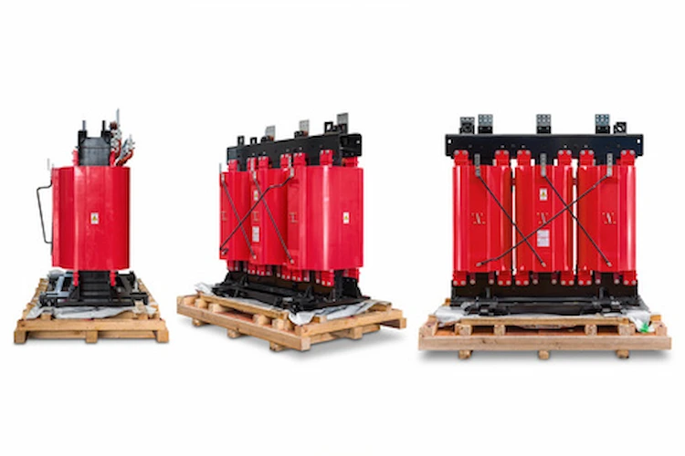
This paper analyzes and studies the two core forms of dry type transformer, compares the cost of round and oblong cores by example, and uses finite element software to calculate and analyze the short-circuit force of different core forms of windings.
In the power system, dry-type transformers can play the role of voltage regulation and stabilization, reduce the role of power transmission losses, occupying a very important link. According to the data, in the distribution transformer losses account for more than 40% of the transmission and distribution losses, and transmission and distribution losses account for about 6.6% of the national power generation.
With the country’s emphasis on energy conservation and environmental protection and the continuous intensification of market competition, the requirements of transformer losses are then higher and higher, and transformer costs are being compressed lower and lower.
At present, in order to save cost, most of the manufacturers have started to use oblong cores to replace round cores as the installation frame of transformers, and at the same time, it has been proved that oblong cores can also achieve the required technical specifications. For this reason, I have analyzed these two core forms for dry-type transformers.
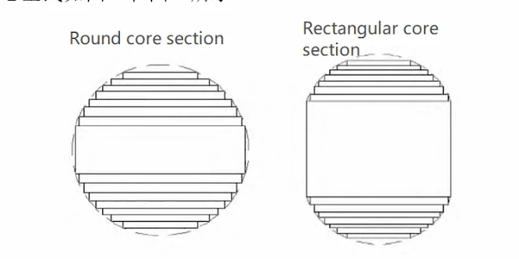
The difference between the round core and the oblong core is that the oblong core is obtained on the basis of the round core and can be used as the basis for calculating the appropriate oblong core. The round and oblong core types are shown in Figures 1 and 2.
In order to study the advantages and disadvantages of the two types of cores, the size and cost analysis of the two types of cores were carried out, and the simulation of the leakage of the dry-type transformer with the two types of cores was carried out by using the three-dimensional model of the finite element software in order to study the advantages and disadvantages of the two types of cores.
Allowable deviation of loss: no-load loss, load loss allowable deviation: +15%; total loss allowable deviation: +10%; short-circuit reactance allowable deviation: ±10%.
According to the technical requirements, electromagnetic calculations are performed. Electromagnetic calculation is an important step in transformer design. The optimized electromagnetic calculation of transformer can reduce production cost, improve product operation performance, reduce product operation loss, and have obvious economic benefits.
The main technical parameters are no-load loss, load loss, impedance, and temperature rise. The main role of the electromagnetic calculation is to guide the structural design (Table 1).
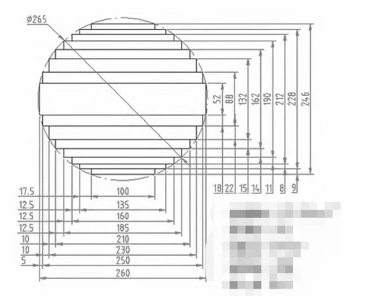
(1) Round core scheme: The core is a three-phase, three-column core with three-stage joints.
The maximum width of the core is 260mm, the thickness of the core laminations is 246mm, and the lamination factor is 0.96. The net cross-sectional area of the core column is 495.36cm2, and the silicon steel sheet is 27QG100.
(2) Rectangular core scheme: The core is a three-phase, three-column core, and a rectangular core is selected. The geometry of oblong core is determined, see Figure 4. 180mm width of core, 300mm thickness of core stack, 0.633 width to thickness ratio, 0.96 stack coefficient, 494.976cm2 net cross-sectional area of core column.
After the completion of the electromagnetic calculation, the main technical indexes of the two schemes were compared, as shown in Table 2.
Through the analysis (Table 3), it is found that in the case of using the same type of silicon steel sheet and wire, and the calculated values of no-load loss, load loss, temperature rise, impedance voltage and other technical indexes are approximately equal, the center distance and copper-iron cost of the round core scheme are higher, and the cost of the long round core scheme is mainly saved in the silicon steel sheet.
When the transformer is running, the high and low voltage coils will be in the strong magnetic field, and when the coil is suddenly short-circuited, the great inrush current will cause the coil to be subjected to huge electromagnetic force. The electromagnetic force is the result of the interaction between the short-circuit inrush current and the leakage magnetic field in the coil, and the excessive electromagnetic force will cause damage to the coil.
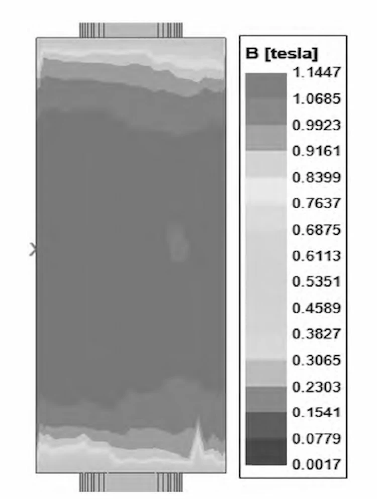
For this reason, we have simulated the transient magnetic field in the case of a short-circuit on the low-voltage side of a dry-type transformer using Ansys Maxwell electromagnetic software, using the finite element analysis method (for a particular phase of the transformer’s low-voltage winding as an example), and the field diagrams are shown in Figures 5 and 6.
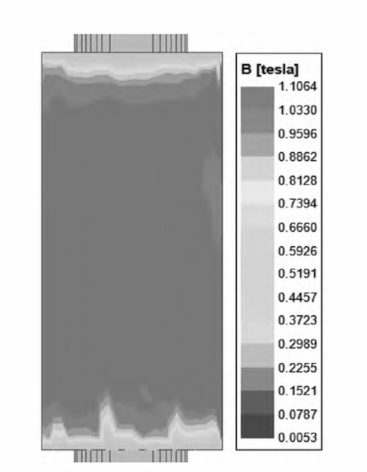
According to the results shown in Fig. 5 and Fig. 6, the axial magnetic leakage distribution is mainly concentrated in the middle of the winding, while the leakage at the two ends of the winding is smaller. The reason for this is that the bending and deformation of the wire at the end of the winding leads to a smaller leakage, which also confirms that the short-circuit force at the ends of the winding is higher.
According to the equation of electromagnetic force for wire short circuit (axial or spoke direction).

Where B0 is the magnetic density corresponding to the steady-state value of the short-circuit current; R is the equivalent radius of the electromagnetic line.
According to the above equation, the short-circuit force is positively related to the leakage magnetic density and the equivalent radius of the electromagnetic wire for a certain short-circuit current. The equivalent radius of the circular core LV winding is calculated to be 209.5mm and the equivalent radius of the oblong core LV winding is 215.927mm for the above two schemes.
Moreover, from the simulation results in Figure 6, the leakage density of the circular core scheme is slightly smaller than that of the oblong core scheme, so as far as the short-circuit resistance of the dry-type transformer is concerned, the circular core scheme is more superior, but the oblong core can also meet the requirements of the users well.
Through the comparative analysis of the two core schemes, it can be determined that compared with the traditional round core, the long round core can save materials and has obvious advantages in terms of size and cost, but the short-circuit resistance is weaker and can also meet the user requirements, while the traditional round core is just the opposite.
Then in order to reduce the cost and occupy more market, it can be expected that there will be more and more oblong core dry-type transformers into the market, while at the same time only continuously optimize the product process, as far as possible to eliminate the impact of the disadvantages, in order to make the oblong core to play the maximum effectiveness.
Download Resource

Table of Contents Selecting the right pad-mounted transformer requires careful consideration of several critical
The primary function of the pad mounted transformer is to serve as a critical distribution
A pad mounted transformer operates through electromagnetic induction, serving as a crucial distribution component that
After filling in the contact information, you can download the PDF.