
How to Choose Pad Mounted Transformer?
Table of Contents Selecting the right pad-mounted transformer requires careful consideration of several critical factors, as these ground-mounted distribution transformers play a vital role
ELECTRIC, WITH AN EDGE
The formula for calculating the transformation ratio of the transformer, the voltage across the primary winding must be the rated value, the primary current I1 of the transformer is determined by the secondary current I2, the current ratio and the number of turns of the primary and secondary sides of the transformer Ratio or voltage ratio is inversely proportional.
In a general power transformer, the winding resistance voltage drop is very small and can be ignored, so the voltage U1=E1 can be considered in the primary winding.
Because the secondary winding is open, the current I2=0, and its terminal voltage U2 is equal to the induced electromotive force E2, that is, U2=E2.
Therefore, from the above transformer ratio formula of induced electromotive force on the primary and secondary sides, we get:
In the transformer ratio formula, K is the ratio of the primary voltage U1 to the secondary voltage U2. The value of this K is called the transformation ratio of the transformer.
The above shows that the voltage ratio of the primary and secondary windings of the transformer is equal to the turns ratio of the primary and secondary windings. Therefore, if the primary and secondary windings have different voltages, just change their turns. When N1>N2, K>1, the transformer step-down; when N1<N2, K<1, the transformer step-up.
For a transformer that has been supported, its K is a fixed value, so the secondary voltage is proportional to the primary voltage, that is to say, the secondary voltage increases as the primary voltage increases, decreases and decreases.
But the voltage across the load primary winding must be rated.
When the applied voltage is slightly higher than the rated voltage, the current passing through the primary winding will greatly increase. If a transformer with a rated voltage of 220V is mistakenly connected to the 380V line, the current of the original winding will increase sharply, causing The transformer burned out.
After the secondary winding load of the transformer is connected, a current I2 flows through the secondary circuit. At this time, the transformer load is called operating.
Since the current I2 in the secondary winding will also generate magnetic flux in the iron core (ie self-induction phenomenon), this magnetic flux will demagnetize the magnetic flux generated by the primary current, that is, in the iron core The magnetic flux should be the combination of the magnetic flux generated by the current in the primary and secondary windings. But under the condition that the applied voltage U1 and the power frequency f remain unchanged, the approximate formula is:
The above transformer ratio formula shows that the resultant magnetic flux Φ should remain basically unchanged. Therefore, with the appearance of I2, the current I1 passing through the primary winding will increase, so that the magnetic flux in the primary winding can avoid the magnetic flux of the secondary winding, and the composite magnetic flux in the iron core remains unchanged on the other side.
The magnitude of the primary current I1 of the transformer is determined by the magnitude of the secondary current I2.
From an energy point of view, the power P1 drawn by the primary coil of the transformer from the power supply should be equal to the output power P2 of the secondary coil (ignoring the transformer’s coil resistance and magnetic flux transmission loss), namely:
It can be seen that the current ratio of the primary and secondary sides of the transformer is inversely proportional to their turns ratio or voltage ratio.
For example, if the number of turns of a transformer N1<N2 is a step-up transformer, the current I1>I2; if the number of winding turns N1>N2 is a step-down transformer, the current I2>I1.
That is, the side with a high voltage has a small current, and the side with a low voltage has a large current.
The above is the calculation formula of transformer transformation ratio.

Table of Contents Selecting the right pad-mounted transformer requires careful consideration of several critical factors, as these ground-mounted distribution transformers play a vital role
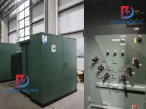
The primary function of the pad mounted transformer is to serve as a critical distribution transformer that steps down higher primary voltage from utility distribution

A pad mounted transformer operates through electromagnetic induction, serving as a crucial distribution component that converts high voltage electricity to lower, usable voltages for residential

When looking for the best pad-mounted transformer manufacturer, it’s important to find industry leaders known for reliability and innovative solutions. Pad-mounted transformers are essential in

After filling in the contact information, you can download the PDF.