How to Choose Pad Mounted Transformer?
Table of Contents Selecting the right pad-mounted transformer requires careful consideration of several critical
ELECTRIC, WITH AN EDGE
The 35 kv 180 MVA large-capacity non-excited regulator oil immersed power transformer described in this paper has a capacity of 180 MVA, which far exceeds the single unit capacity of 35kV oil immersed power transformer specified in the national standard, and is a product for special users.
The increase of single transformer capacity can reduce the loss per unit capacity, reduce power loss, and at the same time, compared with multiple small capacity transformers, the consumables and weight per unit capacity are reduced, which can significantly reduce the one-time investment cost, floor space and maintenance cost, especially in the technical transformation project, the total transformer capacity can be significantly increased with little increase in floor space.
As a result, large-capacity transformers are increasingly used and welcomed by users when conditions permit.
This paper focuses on the design of a 35k V large capacity oil immersed power transformer in terms of voltage regulation and winding type selection.
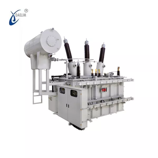
he main technical parameters of 180 MVA/35kV large-capacity oil immersed power transformer are as follows.
Rated capacity: 180/180 MVA
Voltage ratio: 38.5±2×2.5%/10.5kV
Coupling group: YNd11
Short circuit impedance: 14%
Temperature rise limit: winding 65K, top oil 60K
Conventional larger capacity 35kV non-excitation voltage regulation oil immersed power transformer, general high-voltage winding using two-way continuous structure, central regulating, regulating line section in the high-voltage winding directly tapped, low-voltage winding generally using spiral structure.
For capacity up to 180 MVA 35kV large capacity oil immersed power transformer, the total number of turns of high voltage winding is only about 90 turns, using conventional two-way continuous with regulator line section structure, the number of turns per cake is only 2 turns, the number of wires and winding root, winding difficulty, winding eddy current loss and circulating loss is very large, to use self-adhesive transposition wire Winding. Regulating line section to use the kink type, because each cake only 2 turns, and winding the number of roots, winding difficulty is quite large.
The regulating line section is directly tapped on the high-voltage winding, the unbalanced magnetic potential produces large transverse leakage, which not only leads to increased local stray losses, but also makes the winding withstand short-circuit capacity becomes poor, the possibility of mechanical instability becomes larger.
Therefore, for 35kVoil immersed power transformer with capacity up to 180 MVA, if the regulating line section is wound separately as regulating winding and neutral point regulating method is adopted, the high voltage winding can adopt a single spiral structure all the way, which greatly reduces the winding difficulty and improves the safety and reliability of the product.
Figure 1 is a schematic diagram of the structure of the conventional 35kV high-capacity product and the 180 MVA/35kV product described in this paper.
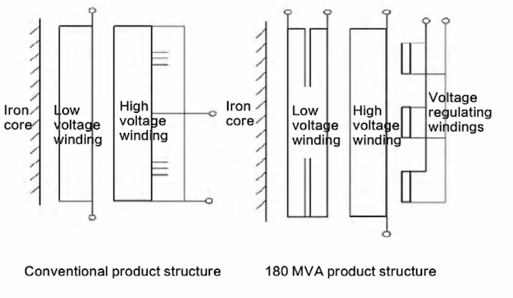
180 MVA/35kV large-capacity oil immersed power transformer after a variety of options to compare, and finally adopted a separate regulating winding structure, neutral point regulation. The winding arrangement from the core outward is: low-voltage winding – high-voltage winding – regulating winding in order.
After a comparison of the main consumables, the separate regulating winding structure is slightly more costly than the direct tap structure of the high-voltage winding, but it is superior in terms of product technical performance, magnetic leakage control and mechanical strength, and has higher product reliability.
The high-voltage winding adopts single spiral type all the way, wound by multiple self-adhesive semi-hard transposition wires, using Pango transposition, and the number of transposition is the number of transposition wires minus 1.
The low-voltage winding adopts double-layer “U” spiral type, with the first and last ends all leaded out at the top of the winding. Compared with the traditional structure, the length of connecting leads is significantly reduced, and the lead loss and stray loss of structural parts caused by high current leads are greatly reduced.
The initial scheme of the regulating winding is spiral, with the upper and lower two circuits connected in parallel. Due to the high capacity and high current of the product, an ordinary single-phase drum tap changer cannot meet the requirements. After repeated negotiations with the switch factory, the final structure of the switch was a three-way parallel connection.
In order to simplify the structure of the regulating winding and switch lead connection, the regulating winding was finally adjusted to a three-way parallel structure, with each way corresponding to one lead of the on-load tap-changer for easy operation and a neat and beautiful lead connection.
The other parts of the transformer have no obvious special features and will not be repeated.
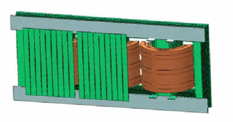
Under the conventional structure, when the regulating winding is two-way parallel, as long as the structure is symmetrical, the current flowing in the parallel two-way is not much different, but under the three-way parallel structure, due to the asymmetric position of the leakage field in the three regulating windings, the impedance is not consistent, the current distributed in each branch may have a large difference.
After simulation calculations, the minimum tap, parallel connection of the three regulating windings in the current distribution is uneven, the largest one in the current reached 1.2 times the average, which should be noted in the winding temperature rise calculation and structure design, to avoid local overheating of the winding.
Table 1 shows the comparison between the calculated and tested values of the main technical parameters of the product.
Table 2 shows the comparison between the 180 MVA/35kVoil immersed power transformer described in this paper and several other 35kVoil immersed power transformers of the same capacity in terms of technical performance indicators and floor space.
From Table 2, it can be seen that the use of one 180 MVA transformer has a great advantage over the use of two 90MVA or three 63MVA transformers in terms of power loss reduction and floor space.
P0/kW | Pk/kW | Floor space/m2 | |
1 set 180 mva transformer | 83.6 | 476.2 | 47.4 |
2 set 90 mva transformer | 46.4 x 2 | 316.9 x 2 | 30.1 x 2 |
3 set 63 mva transformer | 33.7 x 3 | 266.8 x 3 | 23.5 x 3 |
The 180 MVA/35kV large capacity oil immersed power transformer, which has obvious advantages in terms of one-time investment, floor space and power loss, is being used more and more.
In large-capacity product design, the necessary tests or simulations should be conducted for special structural aspects to ensure the technical performance and reliability of the product.
Download Resource

Table of Contents Selecting the right pad-mounted transformer requires careful consideration of several critical
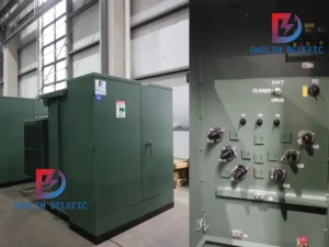
The primary function of the pad mounted transformer is to serve as a critical distribution
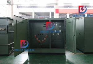
A pad mounted transformer operates through electromagnetic induction, serving as a crucial distribution component that
After filling in the contact information, you can download the PDF.