
How to Choose Pad Mounted Transformer?
Table of Contents Selecting the right pad-mounted transformer requires careful consideration of several critical factors, as these ground-mounted distribution transformers play a vital role
ELECTRIC, WITH AN EDGE
Dielectric loss of power transformer:
1. Dielectric loss is mainly caused by capacitive equipment; the host asked about the dielectric loss of the transformer, which should mainly refer to the magnetic dielectric loss.
2. “The ratio of the out-of-phase component to the in-phase component is called the dielectric loss tangent tanδ.” This sentence may be the opposite of the numerator and denominator.
The current on the ideal capacitor should have only reactive components. With active components, there will be “losses”, so the active components should be molecules.
The formula tanδ=1/ωCR is correct. This is actually the ratio of (1/R) and (ωC), (1/R) is proportional to the active current, and (ωC) is proportional to the reactive current. The dielectric loss is equivalent to a resistor R in parallel with a capacitor.
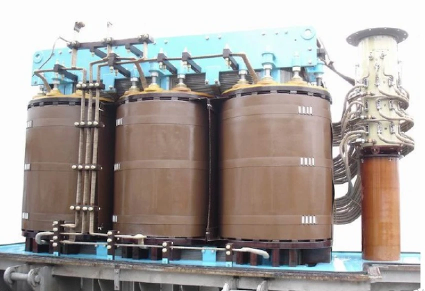
Mainly refers to the loss of magnetic medium. (Transformer loss)
For magnetic medium loss, it mainly includes two parts: one part is hysteresis loss, and the other part is eddy current loss.
The hysteresis loss is because the iron core has a “hysteresis loop”, so that the phase difference between the induced electromotive force and the magnetizing current is not equal to 90 degrees. We know that if it is 90 degrees, the current is “reactive”. Now it is not equal to 90 degrees, which is equivalent to connecting an active current component in parallel.
Eddy current loss is also equivalent to a current component connected in parallel.
When the transformer is working normally, the magnetic field generated by the main part of the secondary side current and the primary measured current is offset. The magnetic field remaining after the cancellation should be roughly equal to the magnetic field at no load (when the secondary current is zero) (assuming ignoring resistance and magnetic leakage).
Therefore, the above “magnetizing current” should be equal to the no-load current of the transformer.
Ideally, the no-load current should be 90 degrees behind the voltage, which is “reactive”.
With the above losses, this lag is not enough to be 90 degrees. The complementary angle δ of this lag angle can also represent the magnitude of the loss.
What is the no load losses of transformer?What is the short-circuit loss of the transformer
When the transformer is no-load, if there is no loss, the input characteristics of the primary side should be equivalent to a pure inductance. With loss, the input current is equivalent to adding a resistor in parallel to the inductance. tanδ should be equal to the ratio of the current on the equivalent resistance to the current on the inductor.

Table of Contents Selecting the right pad-mounted transformer requires careful consideration of several critical factors, as these ground-mounted distribution transformers play a vital role

The primary function of the pad mounted transformer is to serve as a critical distribution transformer that steps down higher primary voltage from utility distribution
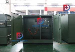
A pad mounted transformer operates through electromagnetic induction, serving as a crucial distribution component that converts high voltage electricity to lower, usable voltages for residential

When looking for the best pad-mounted transformer manufacturer, it’s important to find industry leaders known for reliability and innovative solutions. Pad-mounted transformers are essential in
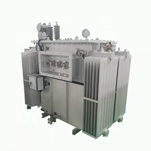
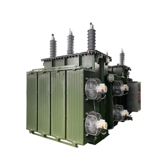
After filling in the contact information, you can download the PDF.